Abstract
Solar energy is the main source of the earth’s energy. It can be converted to different forms of energy such as electric energy. Photo-voltaic (PV) modules are used to convert the sunlight to electricity. However, the angle between the PV module and the ground is one of the important factors that affect the generated power by the module, so it is very important to choose the best angle. In order to get the maximum power of the sun, the PV module should face the sun where the sunlight line has an angel of 90 degree with the surface of the module, in other words, the module should track the sun so the sunlight is perpendicular on the surface of the module. In this project, a vertical-axis solar tracking system will be built to increase the generated power by the PV module and improve the performance so more sunlight can be captured. The University of Bridgeport (UB) will be considered as the location of the system. In this project will be used a light/dark circuit (LDR sensors) in order to detect the sun position and relays switches for the logical unit. The logical unit that control the movement of the module. A linear actuator will be used to move the PV module. The generated power by the PV module will be estimated and compared with/without the tracking system, and analysis for the results.
Project Description
In this project you will be able to design a sun tracking system to increase the captured sunlight so you can get more generated electricity. This system converts solar energy to electricity [DC Electricity] using a moving photovoltaic module . I considered University of Bridgeport, USA as our location to design the system. In this project I will use a light/dark circuit (LDR sensors) in order to detect the sun position and we will use relays switches for the logical unit.
The main required components of our system :
– PV module.
– linear actuator.
– LDR Sensors.
– Relays.
– Testing and measuring tools.
– Wires.
– Other tools.
So in this project we need to use LDR sensors switch circuits so we can detect the sun position.


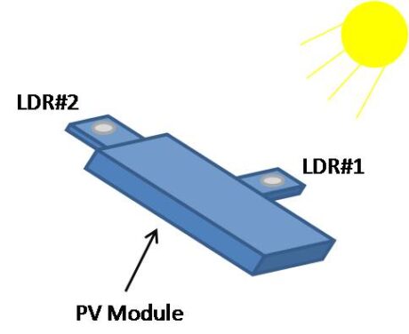
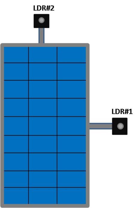
LDR#2: This sensor is intended to detect the light, if there is light or dark (Night/daytime). If it is dark, the sensor will send a signal to the circuit to run the actuator to send the PV module to the initial position (East) and turn LDR#1 circuit off until the sunrise.
LDR#1: This sensor is intended to detect the sun position. A barrier was used beside the sensor so when the sun move toward the west , the sensor will receive shadow so will send a signal to the circuit to run the actuator to move the PV module toward the west tracking the sun until the sensor receive sunlight again, then actuator will stop.
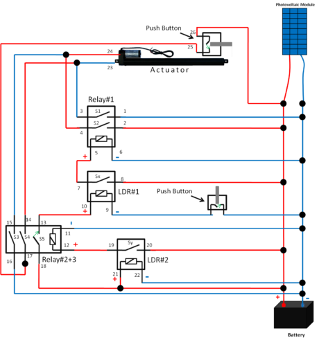
Circuit Diagram of the PV tracker

Description of operation:
When the actuator moves up it rotates the disc so it would make it turn. When the actuator retracts and moves back it would push a stop button that would stop the system till the next time it will need to move. Above I showed the diagrams of the circuit of the LDR and of our entire system, also I showed the circuit diagram for the relays and how they operate. Now after we saw the design and the components used in this project, next I will explain how this entire system operates.
In the morning the sun rises from the east and that means the system is still at a steady position, which means Sy is open. When Sy is open that means relay number 2 is off and that means S3 and S4 are open and s5 is closed. When S5 is closed it gives a signal to LDR 1 which tells it to stand by. When LDR 1 detects light then Sx opens, which means relay number 1 off then s1 and s2 open which gives the actuator a signal to move the panel toward the west until LDR 1 detect light which means PV disc would stop to rotate until the sun goes away again and the LDR can’t detect it. At night there is no sun so what happens is LDR 2 is closed which makes relay number 2 to work. What that means is s3 and s4 is closed which means LDR1 is off, and when that happens the actuator would retract and as it goes back it stops s4 which shuts off the switch and makes the system go back into initial position.
During the night there is no light which means LDR 2 is energized which means Sy is closed, when Sy is close relay number 2 is going to be energized as well. That makes s5 open s4 closed and s3 closed. When the actuator is in the initial position @ 0 that means the push button will be open which means the actuator is going to be off. This situation stays all night as long as there is no sunlight. At the same time at night s5 is opened which means LDR1 is off or unenergized which means Sx is open and relay number 1 is off which means s1 and s2 is opened. In our system LDR 1 and ldr2 are interlocked with one another, LDR 1 will not operate unless LDR 2 is unenergied (has sunlight which means Sy open) however as soon as LDR 2 receive light it will shut off right away and activate ldr1. As the morning begins and the sun start to rise whenever LDR 2 receive sunlight Sy would open then relay 2 becomes unenergized which means s5 is closed and s3 and s4 open. When s5 is closed ldr 1 is at stand by to operate (if there is sunlight Sx open if not Sx closed), as the sun moves west and becomes unperpendicular LDR 1 wont be functional because it will have a shadow on the sensor which makes Sx closed. When Sx closed relay 1 would be energized which means s1 and s2 would close which makes the actuator work and extend forward which drives the rack and pinon to rotate the disc toward the sun which is heading west and it would keep moving until the sunlight shine on the sensor located on Ldr1. As the sun light shine on LDR 1 Sx open and s1 and s2 opens which makes the actuator stops its movement. This situation would keep on going west until the sunsets, after the sun sets and goes away LDR 2 has no sunlight which means Sy would close and relay 2 energized ( s5 open s4 and s3 closed), when relay 2 energized it makes ldr1 unenergiezed which means Sx is open and s2 and s1 is open, which means the actuator won’t extend anymore until the morning and as long as its dark outside all of this is happening because s5 is open in relay 2. When the actuator is not in its initial position (push button is closed) and s4 and s3 is closed then the actuator would retract back into its initial position and it would go back until it it’s the push button and opens it then the circuit would open and that would shut off the actuator. This process would continue on and repeat itself every day.
If you want to use this article for your project you have to mention us as the source. This as a copy righted content.
Author: Taleb H. Al-theanat
1 responses on "A New Vertical Sun Tracking System for a PV Module Using Relays Concept"
Leave a Message
You must be logged in to post a comment.


Great Idea Eng.Taleb.