Key Takeaways
- A voltage regulator is an autotransformer with a motorized tap changer that boosts or bucks line voltage to hold a target value as load varies.
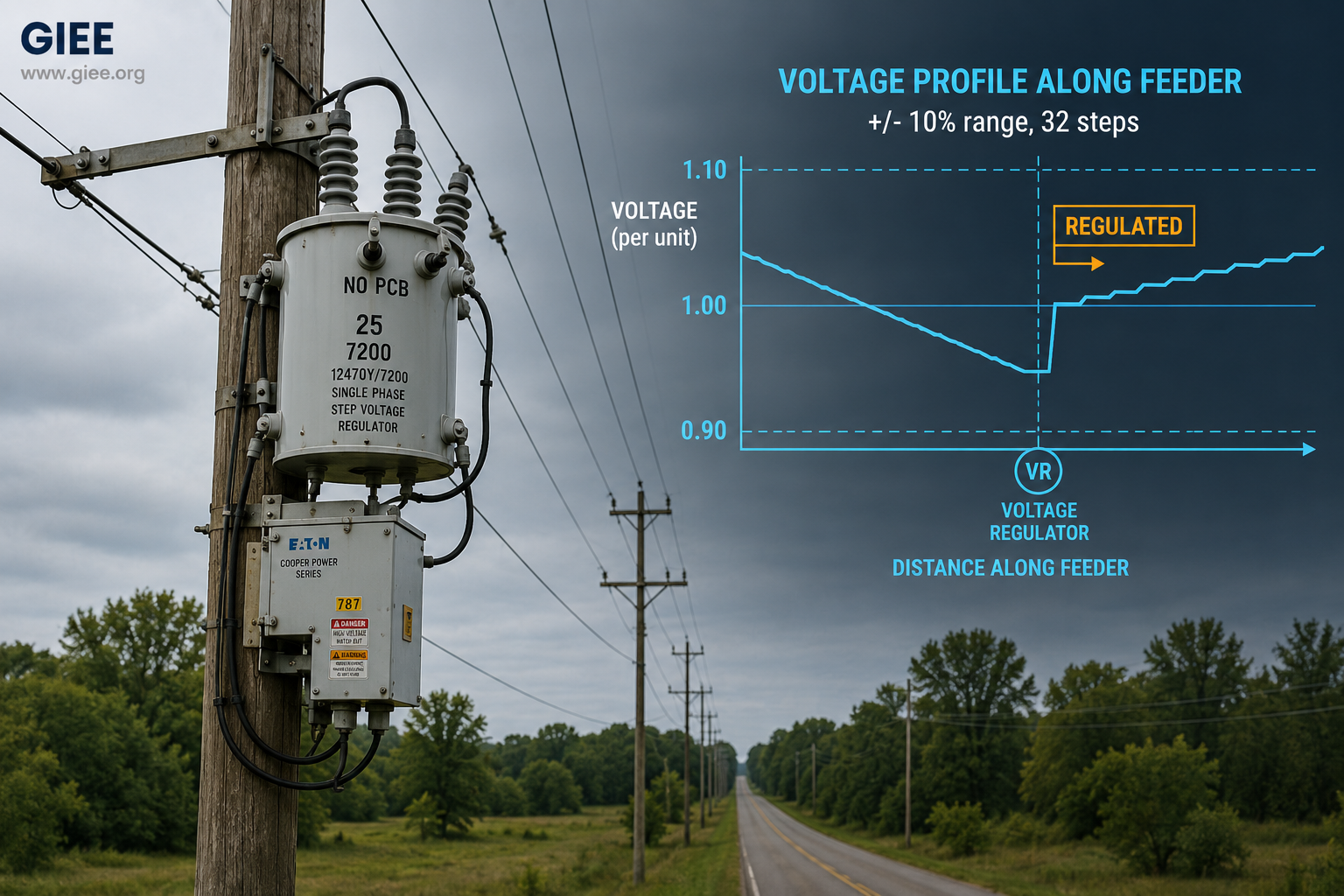
- Distribution step voltage regulators typically cover a ±10% range in 32 steps of 0.625% each, controlled by a voltage-regulating relay.
- Line drop compensation (LDC) lets a regulator hold voltage at a remote load center, not just at its own terminals – the feature that makes long feeders work.
- Regulators keep service voltage inside ANSI C84.1 limits, which protects motors and electronics, reduces losses, and underpins reliability.
- High distributed energy resource (DER) penetration and reverse power flow break naive LDC settings, so controls and placement need to be revisited.
Voltage is the one power-quality parameter that nearly every connected device cares about, and it is also the parameter that drifts the most as a feeder loads up and unloads through the day. Drive a heavily loaded rural circuit at 5 p.m. and the far-end voltage can sag well below nameplate; come back at 3 a.m. with light load and reverse flow from rooftop solar, and the same point can climb above the upper limit. The device that absorbs this swing, quietly and continuously, is the voltage regulator. This article is for distribution and power-systems engineers who want a clear, practical picture of what regulators do, how they hold voltage as load changes, and where they earn their place on real circuits.
The voltage problem on a distribution feeder
Voltage does not arrive at the customer unchanged. As current flows through the resistance and reactance of conductors, transformers, and connectors, voltage drops along the way. On a radial distribution feeder the effect is cumulative: every span adds a little more drop, so the customer at the end of a long circuit sees a lower voltage than the one next to the substation. The approximate drop across a line section is captured by a familiar expression.
Two things make this drop a moving target. First, the current term varies directly with load, so the drop is largest exactly when demand peaks. Second, the reactive component (the X sinφ term) means that inductive loads – motors, in particular – pull voltage down harder than their real power alone would suggest. The engineer’s job is not to eliminate the drop, which is physically baked into the circuit, but to keep the delivered voltage inside an acceptable band at every point and every hour. That band is set by standard.
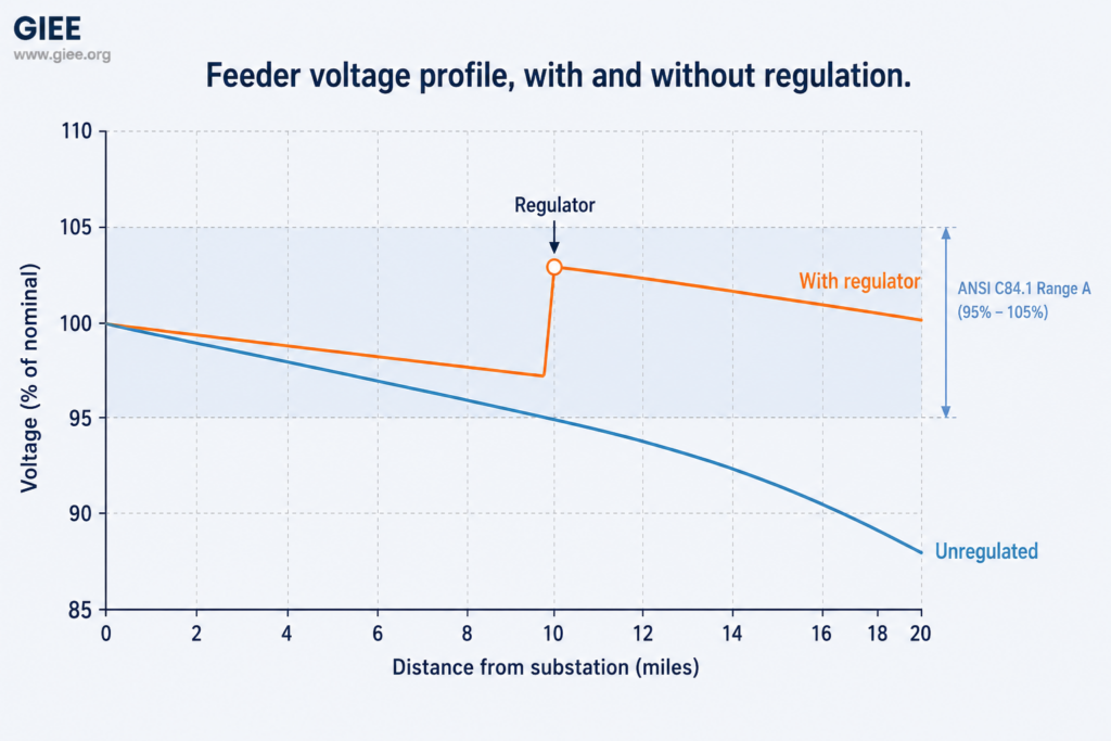
That band comes from standard. ANSI C84.1 defines service voltage ranges for 60 Hz systems: on a 120 V base, Range A normal service is 114–126 V (±5%), with Range B allowing a wider, limited-duration excursion. Expressed on a 120 V reference, the design problem is to keep every customer between 114 V and 126 V whether the feeder is lightly or heavily loaded. On a short, stiff urban circuit, the substation transformer alone may manage this. On a long or lightly built circuit, it cannot – and that is where a dedicated regulator enters.
| ANSI C84.1 (120 V base) | Lower limit | Upper limit | Use |
|---|---|---|---|
| Range A (normal) | 114 V (-5%) | 126 V (+5%) | Sustained service voltage |
| Range B (limited) | 110 V (-8.3%) | 127 V (+5.8%) | Short, infrequent excursions |
What a voltage regulator actually is
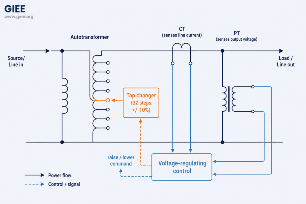
Strip away the packaging and a distribution step voltage regulator is an autotransformer with a motor-driven tap changer and a brain. The autotransformer adds a controllable series voltage to the line – boosting when the line is low, bucking when it is high. The tap changer, an under-load (on-load) mechanism, moves between taps without interrupting service. The brain is a voltage-regulating control that measures the output voltage and decides when to step.
The numbers are worth committing to memory because they recur in every regulator setting sheet. A standard distribution regulator spans a ±10% range in 32 steps – 16 boost and 16 buck – which works out to 0.625% (5/8%) per step on the regulated winding. Units come single-phase, ganged into banks for three-phase circuits, or as integrated three-phase regulators, and are governed by IEEE C57.15. The same boost-or-buck concept also appears as the load tap changer (LTC) built into many substation power transformers; a standalone line regulator simply puts that capability out on the feeder where the drop is happening.
Holding voltage steady as load changes
The control loop is what turns a tap-changing autotransformer into a regulator. The voltage-regulating relay compares the measured output voltage against a set point and acts only when the measured value leaves a defined bandwidth – commonly on the order of 2 V on a 120 V base, or about ±1 V around the target. A built-in time delay (often 30 to 60 seconds) ensures the regulator responds to genuine load trends rather than momentary fluctuations, and it is the single most important setting for preventing hunting, the wasteful back-and-forth tap cycling that shortens mechanism life.
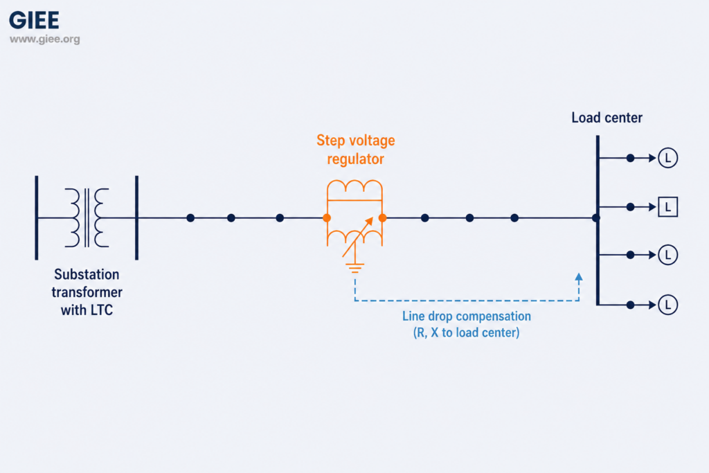
The feature that unlocks long feeders is line drop compensation. Instead of regulating its own terminal voltage, the regulator uses the current measured by its CT together with resistance and reactance settings (R and X dialed in to represent the line out to a chosen load center) to estimate the voltage at that remote point. It then regulates as if it were standing there. The practical result: at light load the regulator holds a modest output, and as load builds and the real far-end voltage would sag, LDC tells the regulator to boost further. One device, correctly compensated, keeps a distant load center in band across the full daily load curve.
Where regulators earn their keep
The clearest case is the long rural distribution feeder. A circuit running 30 or more miles through low load density accumulates enough drop that the substation transformer alone cannot serve the tail end within Range A at peak. Utilities address this by placing one or more regulators in series along the feeder, each compensated to its own downstream load center, effectively re-baselining the voltage at intervals so the profile saw-tooths back up instead of sliding ever lower. It is common to see two or even three regulator stations cascaded on a single long rural backbone.
Industrial loads stress voltage in a different way. Large motor starting draws several times running current at poor power factor for a few seconds, and that inrush pulls voltage down sharply through the X sinφ term. A regulator helps hold the steady-state level for the surrounding circuit, but its tap-changing speed and time delay are not designed to catch a sub-second starting dip – that is the domain of soft starters, dedicated reactive support, or stiffening the supply. The lesson for the practitioner is to match the device to the timescale of the disturbance: regulators for slow load-following swings, faster reactive devices for transient events.
Rural and remote networks also illustrate the reliability payoff. Voltage held within band is not a cosmetic nicety – induction motors overheat and lose torque at low voltage, electronic supplies and LED drivers misbehave at the extremes, and sustained over-voltage shortens equipment life. Keeping voltage in the middle of the band also trims distribution losses and enables conservation voltage reduction (CVR) programs, where a utility deliberately operates toward the lower end of Range A to shave demand. None of that is possible without confident, continuous voltage control.
Limits, trade-offs, and the DER complication
Regulators are robust and well understood, but they are not a universal answer. They are electromechanical: each tap operation wears the mechanism, so tap-change counters are a genuine maintenance metric, and a poorly tuned control that hunts will consume that life quickly. They correct slow swings, not transient dips or harmonics. And because each unit regulates toward its own compensated point, coordinating several regulators in series – and coordinating them with substation LTCs and switched capacitor banks – takes deliberate study to avoid devices working against one another.
The sharpest modern challenge is high DER penetration. Behind-the-meter solar can push midday voltage up and even reverse power flow on the feeder, inverting the assumptions baked into traditional forward-flow LDC settings. The response is partly better controls (bidirectional-aware regulators, communication-enabled coordination, and increasingly DER smart-inverter volt-var support under IEEE 1547-2018) and partly better planning, including hosting-capacity analysis that tests voltage under minimum-load-with-maximum-export. The regulator remains central, but it now operates as one element in a more actively managed voltage scheme rather than a set-and-forget box on a pole.
Conclusion
A voltage regulator does one job extremely well: it injects a controllable series boost or buck so that delivered voltage stays inside ANSI C84.1 limits while load and source conditions move beneath it. On long feeders, lightly built rural networks, and circuits feeding heavy industrial load, that capability is what makes compliant, reliable service possible – and line drop compensation is the setting that turns a local device into feeder-wide control. The next step for any engineer working these circuits is to pull the regulator setting sheets and confirm the bandwidth, time delay, and LDC R and X values still reflect today’s load shape, today’s load center, and today’s level of distributed generation. The hardware rarely fails the feeder; stale settings do.