

Key Takeaways
- Tabulated ampacity is valid only at the reference conditions it was derived for: a fixed ambient, a single circuit, and a defined installation method.
- Derating factors adjust that number for heat that cannot escape – higher ambient temperature, grouped cables, restrictive installations, and poor thermal environments.
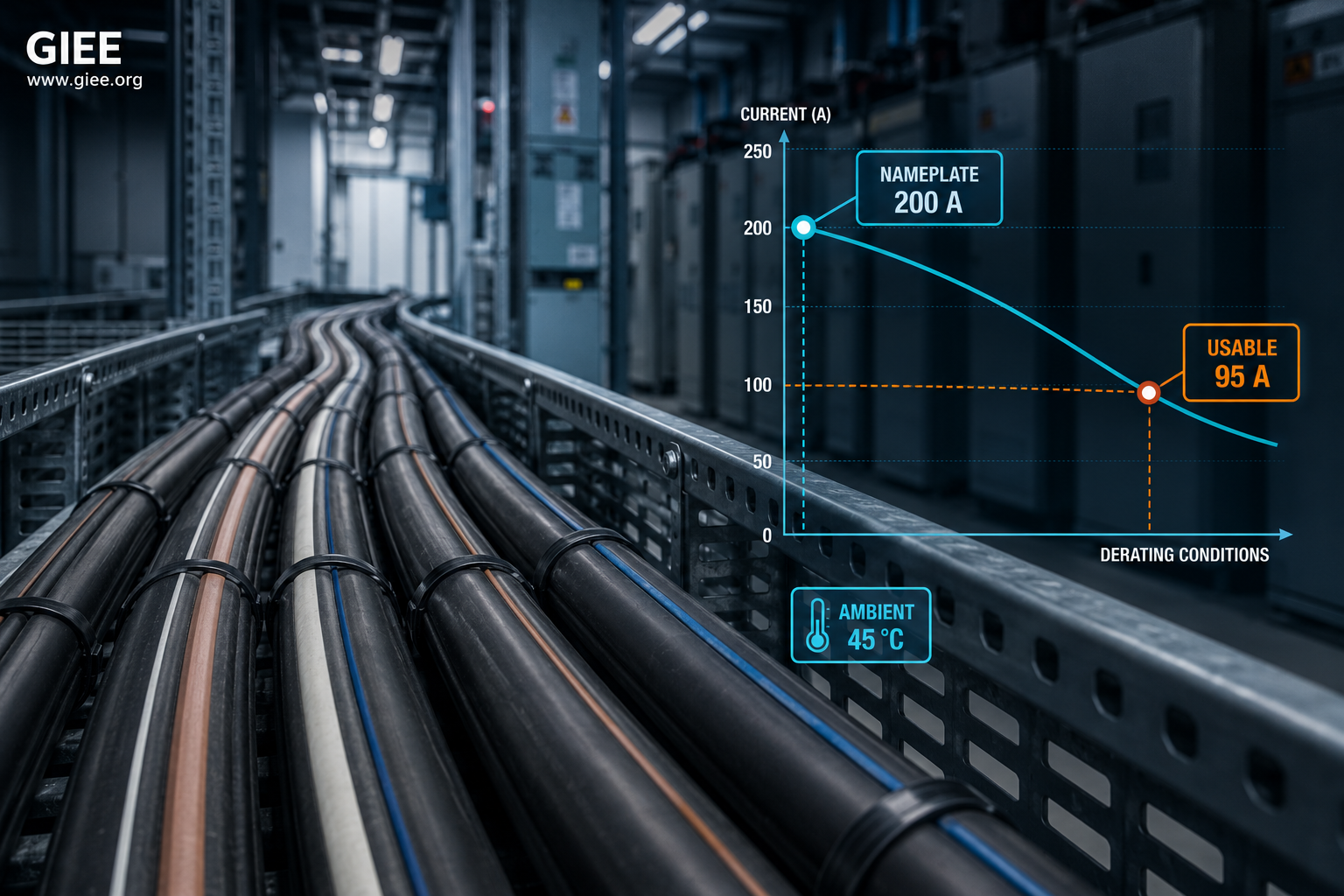
- Factors multiply. A hot, crowded run can leave a cable carrying barely half its nameplate rating.
- Solar PV, battery energy storage, and industrial plants concentrate the very conditions that drive the deepest derating.
- Ignoring derating does not trip a breaker – it quietly ages insulation and raises the risk of thermal failure years later.
An engineer opens a manufacturer datasheet, reads “200 A,” and sizes the circuit. The number feels authoritative, and it is – for the exact conditions under which it was calculated. The problem is that almost no real installation matches those conditions. Cables in a solar combiner run bake on a rooftop. Feeders in a data center share a crowded tray. Battery energy storage system (BESS) DC cables carry high continuous current inside a warm enclosure. In every case, the tabulated ampacity is an optimistic ceiling, not a usable rating.
This article explains what cable derating is, why it exists in physics rather than in code bureaucracy, and how much it can cost you in usable capacity. It is written for practicing electrical, power, and renewable-energy engineers who already know Ohm’s law and want to sharpen their engineering judgment around real-world cable ratings.
What Nameplate Ampacity Really Means
Ampacity is the continuous current a conductor can carry without its insulation exceeding a rated temperature limit. That limit is a material property: 70 °C for standard PVC insulation, 90 °C for cross-linked polyethylene (XLPE) and EPR. Exceed it continuously and the insulation ages faster, embrittles, and eventually fails.
Critically, every tabulated ampacity in IEC 60364-5-52, NEC Table 310.16, or IEEE Std 835 assumes a specific set of reference conditions: a defined ambient temperature (commonly 30 °C in air or 20 °C in soil), a single isolated circuit, and one installation method. Change any of those, and the heat balance that produced the number changes with it.
The Physics: Heat In, Heat Out
A loaded conductor is a small, distributed heater. The power it dissipates is P = I²R – proportional to the square of current. Double the current and you quadruple the heat. That heat must leave the conductor by conduction, convection, and radiation into the surroundings. The conductor settles at whatever temperature makes heat-in equal heat-out.
Ampacity is simply the current at which that equilibrium temperature reaches the insulation limit. Two levers move it: how hot the surroundings already are (the starting point), and how easily heat can escape (the thermal resistance of the path out). Derating factors are nothing more than corrections to those two levers.
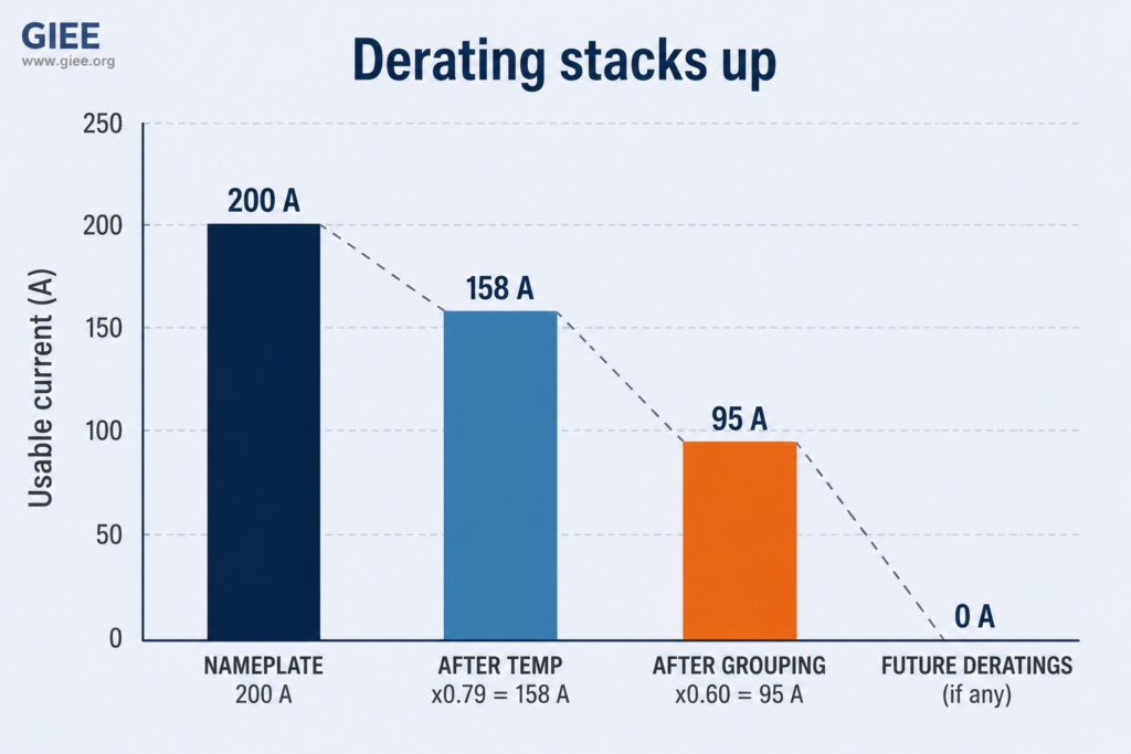
The factors are multiplicative, and that is the single most important thing to internalize. Each one alone looks modest. Stacked together, they compound quickly.
The Factors That Erode Ampacity
1. Ambient temperature
The tabulated rating assumes a modest ambient. Raise the surrounding temperature and you shrink the gap between “starting point” and “insulation limit,” so less current is allowed. A cable rated at 30 °C ambient loses roughly a fifth of its capacity by 45 °C, and close to a third by 50 °C. In hot climates, engine rooms, and unventilated risers, this factor alone is decisive.
| Ambient temperature (°C) | Correction factor k_t (illustrative, 90 °C XLPE) |
|---|---|
| 25 | 1.03 |
| 30 (reference) | 1.00 |
| 40 | 0.87 |
| 45 | 0.79 |
| 50 | 0.71 |
| 55 | 0.61 |
Values are illustrative and rounded for teaching. Use the correction tables in the governing standard for design.
2. Grouping and bundling
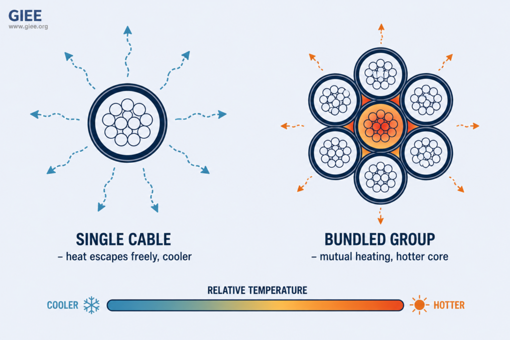
When cables run side by side, each one warms its neighbors. The heat a single cable would shed easily now has to fight through the thermal field of the whole group. The more circuits bundled together, and the more tightly they touch, the deeper the reduction. Six loaded circuits sharing a tray can pull each cable down to around 60 percent of its isolated rating.
| Number of loaded circuits (touching) | Grouping factor k_g (illustrative) |
|---|---|
| 1 | 1.00 |
| 2 | 0.80 |
| 3–4 | 0.70 |
| 5–6 | 0.60 |
| 7–9 | 0.50 |
Spacing cables by one diameter dramatically reduces this penalty, which is why disciplined tray layout is an engineering decision, not a cosmetic one.
3. Installation method
How a cable is routed determines how freely it breathes. A conductor spaced in open air is the best case. Put it in conduit and you add a stagnant air layer; bury it and heat must travel through soil; stack conduits into a duct bank and each cable heats the whole block. The method sets the baseline thermal resistance before any other factor applies.
| Installation method | Heat dissipation | Relative ampacity | Dominant concern |
|---|---|---|---|
| Single cable, spaced in free air | Excellent | Highest (reference best case) | Ambient only |
| Spaced on a cable tray | Good | High | Ambient, mild grouping |
| Bundled on a cable tray | Moderate | Reduced | Grouping |
| In conduit in air | Moderate | Reduced | Trapped air, fill |
| Direct buried | Depends on soil | Variable | Soil thermal resistivity, depth |
| In a buried duct bank | Poor | Lowest | Mutual heating, soil, depth |
4. The thermal environment
The last factor is the medium the heat flows into. For buried cables, soil thermal resistivity dominates: well-compacted moist soil at roughly 0.9 K·m/W conducts heat well, while dry sandy backfill above 2.5 K·m/W behaves almost like insulation and can force a large reduction. Burial depth adds to it – deeper cables are cooler at the surface but slower to shed heat. Outdoors, solar gain raises the effective ambient of exposed conduit, which is why rooftop solar runs are penalized so heavily.
How Derating Stacks Up
Consider a common industrial situation. The factors below are modest individually, but watch the combined result.
Combined temperature and grouping derating can reduce a conductor’s usable current to roughly 45–55 percent of its tabulated ampacity – a factor of nearly two that never appears on the datasheet.
Where This Bites: Sector Examples
Commercial buildings. Riser shafts and shared trays concentrate feeders for tenants, elevators, and mechanical plant. Grouping is the usual culprit, and unventilated risers raise ambient on top of it. A tidy-looking bundle of parallel feeders can hide a 30–40 percent reduction.
Industrial facilities. Plants combine high ambient temperatures, long conduit runs, and dense trays. Variable-frequency drives add harmonic currents that increase effective heating beyond the fundamental, quietly pushing conductors hotter than the sine-wave rating suggests.
Solar PV systems. DC string and combiner cables often run in conduit clipped to a hot rooftop. Surface temperatures can add 20–30 °C to the effective ambient, and standards apply explicit adders for conduit above a roof. A cable comfortable at 30 °C may be operating as if the ambient were 60 °C or more.
Battery energy storage systems (BESS). BESS DC cables carry high, sustained charge and discharge currents inside enclosures where several runs share limited space and the internal ambient is already elevated. Continuous duty, tight bundling, and warm enclosures combine into one of the harshest derating environments in modern power engineering.
Utility-scale projects. Medium-voltage collector circuits are frequently installed in buried duct banks where mutual heating and soil resistivity dominate. Here the accepted practice is a full thermal calculation using the Neher-McGrath approach (the basis of IEC 60287 and IEEE 835) rather than a simple table lookup, because the interactions are too strong to approximate.
Common Misconceptions and Lessons Learned
Three beliefs cause most field problems. First, that the datasheet number is a fixed property of the cable – it is not; it is a property of the cable and its conditions. Second, that if the breaker does not trip, the cable is fine – overheating from under-derating rarely trips protection, because the current stays below the device rating even while the conductor cooks. Third, that a small overload is harmless – insulation life is roughly halved for every 8–10 °C of sustained overtemperature, so the damage is cumulative and invisible until failure.
The practical lesson from real projects is that derating is a routing and layout problem as much as a sizing problem. Spacing cables, splitting large bundles across separate trays, choosing better backfill for buried runs, and ventilating risers often recover more capacity at lower cost than simply jumping to the next conductor size.
Trade-offs and Limitations
Derating is not a matter of always assuming the worst. Over-conservative factors inflate conductor size, cost, and copper use, and can make cable pulling harder in congested routes. The engineering skill is matching the factors to the genuine conditions the cable will see, including realistic future loading rather than nameplate peaks that never occur together.
Standard correction tables also have limits. They assume typical geometries and steady-state, continuous loading. For duct banks, mixed circuit sizes, or cyclic loads such as EV charging and BESS duty, table lookups understate the interactions, and a full thermal calculation or a dynamic (real-time) rating method is warranted. Knowing when the simple approach stops being valid is itself a mark of engineering judgment.
Conclusion
Nameplate ampacity is a starting point, not an answer. It tells you what a conductor can carry in a laboratory-defined world of one cable, one temperature, and one installation. Real projects violate all three assumptions at once, and the physics of heat responds accordingly. The engineer’s job is to read those conditions honestly, apply the right correction factors, and remember that they multiply. Get it right and the system runs cool and lasts decades; get it wrong and the failure arrives quietly, years later, with no warning from the breaker.
To build fluency with the correction tables, installation methods, and thermal calculations behind these decisions, explore the GIEE power systems design curriculum and our companion guide on conductor sizing and short-circuit withstand.