Key Takeaways
- Real power (W) does useful work, reactive power (VAR) sustains magnetic and electric fields, and apparent power (VA) is what the system must physically deliver.
- Power factor is the ratio of real to apparent power, PF = cos φ for sinusoidal conditions, and it sets how much current a load draws for a given amount of useful work.
- Inductive loads – motors, transformers, induction heating – draw lagging reactive current, and a lightly loaded motor can sit at a power factor of 0.5 to 0.7.
- Poor power factor raises line current inversely with PF, which drives I²R losses up with the square, deepens feeder voltage drop, and consumes transformer and cable capacity.
- Correction with shunt capacitors or active front-end drives is effective but introduces harmonic resonance and overvoltage risks that must be engineered against.
Why This Matters Right Now
Electrification is pushing more current through the same copper. As facilities add variable-frequency drives, heat-pump plant, and motor-driven process loads, the reactive component of that current keeps climbing – and so do the demand charges, conductor losses, and voltage problems that follow it. Power factor is the single number that tells you how efficiently a load converts the current it draws into useful work. Get it wrong and you pay for amps that do no work.
This article builds the concept from first principles for working engineers: the three kinds of power, what power factor actually measures, why inductive loads degrade it, and what poor power factor costs a distribution system in hard numbers.
Real, Reactive, and Apparent Power
In an AC circuit, instantaneous power swings as voltage and current vary through the cycle. When you average that over time, the energy splits into two distinct parts.
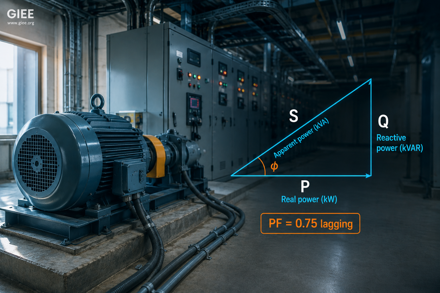
Real power (P), measured in watts (W), is the part that does useful work: shaft torque, process heat, light, computation. Reactive power (Q), measured in volt-amperes reactive (VAR), is the part that shuttles back and forth between the source and the magnetic fields of inductors or the electric fields of capacitors. Averaged over a cycle it performs no net work, yet it still requires real current to flow in the conductors. Apparent power (S), measured in volt-amperes (VA), is the product of RMS voltage and RMS current that the system must physically deliver – the quantity transformers and cables are actually rated against.
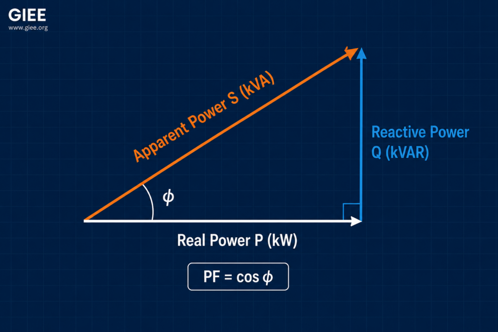
These three combine as vectors, not scalars. Real and reactive power sit at right angles, and apparent power is the hypotenuse. That is the power triangle.
What Power Factor Measures
Power factor is the ratio of real power to apparent power. Under clean sinusoidal conditions it equals the cosine of the phase angle between voltage and current.
A purely resistive load – a heater element – has voltage and current in phase, so φ is zero and PF is 1.0. Real loads rarely behave that well. When current lags voltage, as it does with inductive equipment, the power factor is lagging. When current leads, as with lightly loaded capacitor banks or some power-electronic loads, it is leading.
The reason this matters is structural: the grid sizes and meters its hardware on apparent power, not real power. A transformer rated 1,000 kVA can deliver 1,000 kW only at unity power factor. At 0.8 PF the same transformer is full at 800 kW of useful output, with the remaining 600 kVAR of capacity consumed by reactive current. Many utilities reflect this directly by billing demand in kVA or applying a power-factor penalty below a threshold such as 0.90 or 0.95.
Why Inductive Loads Drag Power Factor Down
Motors and transformers work by establishing a magnetic field, and that field must be energized every cycle. The current that magnetizes the iron lags the applied voltage by close to 90 degrees and contributes almost pure reactive power. This is unavoidable physics, not a defect.
The practical problem is part load. An induction motor draws roughly the same magnetizing current whether it is fully loaded or barely loaded, while the real-power component scales with mechanical output. A motor running at full nameplate load may sit at 0.85 to 0.90 PF, but the same motor at a quarter load can fall to 0.5 to 0.65. Oversized motors, idling pumps, and lightly loaded conveyors are some of the most common sources of poor facility power factor. Transformers under light load, induction furnaces, arc welders, and older magnetic-ballast lighting all behave similarly.
What Poor Power Factor Costs a System
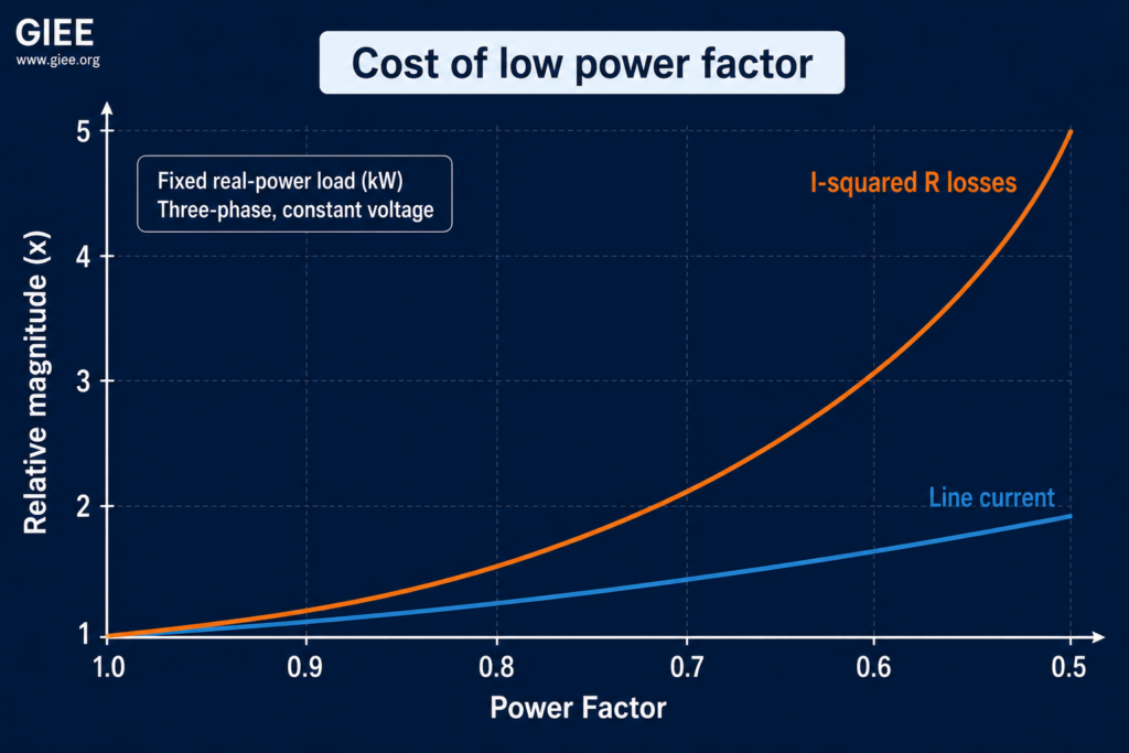
The damage from low power factor traces back to one mechanism: for a given amount of real power, lower PF forces more current through every element between the source and the load. Rearranging the three-phase power relationship makes the dependence explicit.
Current scales inversely with power factor. Drop PF from 0.95 to 0.75 and the current rises by about 27 percent for the same useful output. Four consequences follow.
Increased current. Every conductor, breaker, and contact in the path carries the extra reactive current, even though it delivers no additional work to the load.
Higher losses. Conductor losses follow I²R, so they rise with the square of current. A 27 percent current increase raises resistive losses by roughly 60 percent. In a large plant with long feeder runs, that is real money burned as heat in the cabling.
Voltage drop. Larger current produces a larger I·Z drop along the feeder. Motors at the end of a long run see depressed terminal voltage, and because induction-motor torque varies with the square of voltage, a sagging bus can stall starting and degrade process performance.
Reduced capacity and efficiency. Reactive current consumes headroom in transformers, switchgear, and cables that are rated in kVA. Capacity spent moving VARs is capacity unavailable for growth, and the facility’s overall delivered efficiency falls while demand charges climb.
Correcting Power Factor – and the Trade-offs
Because the problem is excess lagging reactive current, the fix is to supply that reactive power locally rather than draw it across the whole network. Shunt capacitor banks are the workhorse: installed at the bus or near large motor loads, they source leading VARs that cancel the lagging VARs the inductive load demands, so the upstream system sees a near-unity load. Synchronous condensers and the active front ends on modern variable-frequency drives achieve the same end electronically and can correct dynamically.
The trade-offs are where engineering judgment earns its keep. A capacitor bank and the system inductance form a resonant circuit, and if that resonance lands near a harmonic produced by drives or rectifiers, currents can amplify destructively – the reason harmonic studies and detuned or filtered banks exist, and the reason IEEE Std 519 sets limits on harmonic distortion. Overcorrecting into a leading power factor can drive bus voltage up, especially under light load when capacitors stay energized but the inductive demand falls away. And under distorted, non-sinusoidal conditions the simple cos φ relationship breaks down; true power factor then includes a distortion component, which is why IEEE Std 1459 separates displacement power factor from total power factor. For more on that distinction, see our explainer on harmonics and IEEE 519, and on motor behavior under varying supply, our guide to motor starting and inrush current.
Conclusion
Power factor is not an abstraction – it is the dial that sets how much current your system carries for the work it actually performs. Real power does the work, reactive power sustains the fields that inductive equipment needs, and apparent power is the bill the grid presents you. Low power factor quietly inflates current, multiplies losses, sags voltage, and eats the capacity you paid for. Measure it at the loads that dominate your demand, understand how it shifts with part load, and correct it where the engineering supports it – watching for harmonic resonance and overcorrection as you go. Start by pulling power factor from your utility bill and your largest feeders; the gap between what you draw and what you use is usually the cheapest efficiency you will ever find. For a structured path through these fundamentals, explore the GIEE course catalog.