
Key Takeaways
- The per-unit (pu) system expresses every electrical quantity as a fraction of a chosen base value, turning volts, amps, and ohms into dimensionless numbers.
- Pick two bases — apparent power (
S_base) and voltage (V_base) — and the base current and base impedance follow directly.- Its biggest payoff: transformer turns ratios disappear, so a multi-voltage network collapses into one clean reference frame.
- Most per-unit errors aren’t conceptual — they come from sloppy base conversion or mixing single-phase and three-phase quantities.
Introduction
Open any short-circuit or load-flow case in PSS/E, ETAP, or PowerWorld and you’ll see it immediately: line flows, bus voltages, and machine reactances reported not in MW and kV, but as numbers hovering around 1.0. That’s the per-unit system at work. It’s one of the first conventions every power engineer absorbs and one of the easiest to use carelessly.
This article is for working engineers who use per-unit results daily but want a sharper grip on the mechanics — particularly the base-conversion step where most mistakes hide. We’ll cover what problem the system solves, how to build a consistent base, where it shows up on the job, and the trade-offs worth knowing.
The Problem This Solves
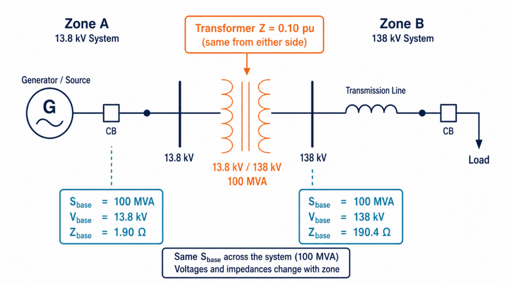
A realistic power system spans several voltage levels — say 345 kV transmission, 138 kV sub-transmission, 13.8 kV distribution — stitched together by transformers. Work in actual units and every transformer forces you to refer impedances across its turns ratio, squaring the ratio each time. Trace a fault current through three transformers and the bookkeeping alone invites errors.
The per-unit system removes that friction. By normalizing each quantity to a base appropriate for its location in the network, the transformer turns ratio cancels out (assuming the voltage bases are chosen to match the nominal ratios). A transformer’s series impedance becomes the same per-unit value whether you view it from the high side or the low side. The 345 kV and 13.8 kV portions of the network suddenly live in the same numerical world.
There’s a second, quieter benefit: per-unit values are intuitive. A bus at 0.94 pu is obviously low; a transformer at 0.10 pu impedance is unremarkable; a generator at 4.5 pu fault current is a familiar magnitude. The numbers themselves carry engineering judgment.
How It Works
The whole system rests on one definition:
per-unit value = actual value / base value
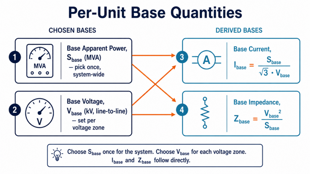
You only need to choose two bases; the rest are derived. The standard choice in power system studies is a system-wide apparent power base, S_base (the same number everywhere — commonly 100 MVA), and a voltage base, V_base, set per voltage level to the nominal line-to-line voltage of that zone.
From those two, base current and base impedance follow. For a three-phase system, using line-to-line voltage and three-phase power:
I_base = S_base / (√3 · V_base)
Z_base = V_base² / S_base
A worked example makes this concrete. Take S_base = 100 MVA on the 138 kV bus. Then:
Z_base = (138 kV)² / 100 MVA = 190.4 Ω
A transmission line with 19 Ω of series reactance is therefore 19 / 190.4 ≈ 0.10 pu — a tidy, checkable number.
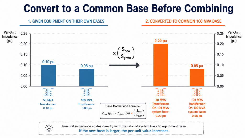
The step that trips people up is changing base. Equipment impedances are published on the manufacturer’s nameplate base (its own MVA and voltage rating), which rarely matches your study base. Convert with:
Z_pu,new = Z_pu,given · (V_given / V_new)² · (S_new / S_given)
So a 50 MVA transformer rated at 10% impedance on its own base, placed in a 100 MVA study, becomes:
Z_pu = 0.10 · (100 / 50) = 0.20 pu
Skip that conversion and your fault currents will be off by exactly the base ratio — a silent, plausible-looking error.
💡 Practitioner Tip: Pick one
S_base(100 MVA is the near-universal default) and lock it for the entire study before you touch a single impedance. Then set each zone’sV_baseto the nominal voltage, and verify your voltage bases match the transformer turns ratios — that match is what makes the ratio cancel.
Real-World Application
Per-unit isn’t an academic nicety — it’s baked into how the industry specifies and analyzes equipment.
Nameplate impedance. Transformer and generator ratings list impedance as a percentage (percent impedance is simply per-unit × 100, on the equipment’s own base). A “10% impedance” 138/13.8 kV transformer is telling you its series reactance is 0.10 pu — directly usable once you convert to the study base. This convention, formalized in equipment standards and analysis guides such as IEEE Std 399 (the Brown Book) and IEC 60909 for short-circuit calculation, lets engineers compare a 5 MVA distribution transformer and a 500 MVA generator step-up unit on the same scale.
Short-circuit studies. Fault analysis is where per-unit earns its keep. With every reactance referred to a common base, the fault MVA at a bus is found from the Thevenin equivalent per-unit reactance: Fault MVA ≈ S_base / X_pu. A bus seeing 0.05 pu source reactance on a 100 MVA base has roughly 2,000 MVA of fault duty — a one-line mental calculation that would be tedious in ohms.
Voltage and protection. Operators and planners read bus voltages in per-unit against the limits in ANSI C84.1, and relay settings, power-flow reports, and stability studies all ride on the same normalized framework. (For a deeper treatment of fault duty, see our guide to short-circuit analysis on distribution systems.)
Limitations and Trade-offs
The per-unit system is robust, but a few sharp edges remain.
The most common failure is base inconsistency — mixing values referred to different S_base or V_base choices in one calculation. Because every per-unit number looks reasonable, the error rarely announces itself; it surfaces as a fault current that’s wrong by a clean integer ratio.
A close second is confusing single-phase and three-phase bases, or mixing line-to-line and line-to-neutral voltage. The three-phase formulas above assume line-to-line voltage and three-phase power; combine them with a per-phase quantity and a √3 sneaks in or drops out.
⚠️ Common Mistake: Treating an off-nominal transformer tap as if the turns ratio still matches the voltage bases. When a transformer is tapped away from nominal, the ratio no longer cancels cleanly, and you must model the off-nominal tap explicitly (an ideal tap ratio in series with the impedance) rather than assuming the per-unit impedance is symmetric.
Finally, per-unit hides physical units, which is a feature until it isn’t. When you need to size a conductor, set a CT ratio, or order a breaker, you must convert back to amps and ohms — and that round trip reintroduces the very base arithmetic per-unit was meant to simplify. Unbalanced and zero-sequence work adds further nuance, since sequence networks each carry their own base bookkeeping.
Conclusion
The per-unit system is less a calculation trick than a coordinate change: pick a sensible S_base and per-zone V_base, derive current and impedance, and a multi-voltage network becomes a single, transformer-free reference frame. The concept is simple; the discipline is in the base management. Lock your bases early, convert nameplate impedances deliberately, and keep your three-phase and line-to-line conventions straight — and per-unit will do exactly what it was designed to do.