On a utility-scale ground-mount site, the photovoltaic (PV) source-circuit and combiner conductors have to travel from the modules to the inverters. Trenching every run is slow and costly; spanning long gaps with cable tray is heavy and structurally demanding. Messenger wire — a tensioned support cable that carries the conductor bundle through open air between racking structures — is the workhorse for the inter-table and inter-row sections of the array.
It is also one of the most frequently under-engineered details on the job. Over-tension the run and you overload the racking and piles. Under-tension it and the bundle sags into standing water, snow, or the path of a mower. Both failures are avoidable with a short sag-tension calculation and a few deliberate hardware choices. This guide covers the mechanics, the ampacity treatment, the applicable code, and the field details that separate a clean install from a callback.
- Messenger wire is a structural element first and a wiring method second. Its tension is a real horizontal load the racking and end posts must be designed to carry.
- Size the messenger from a sag-tension analysis at the governing load case (cold-plus-ice, or wind), never by habit. The parabolic approximation is accurate for the shallow sags used in practice.
- Set sag, not tension, in the field, keyed to the recorded ambient temperature. Tension rises as temperature falls — the cold case usually governs.
- Messenger-supported conductors earn free-air ampacity only if they keep their spacing. A tight lashed bundle forfeits it and triggers NEC bundling adjustment factors.
- Treat the messenger as part of the bonding system where code requires, and avoid galvanic pairs in the hardware. These two details drive most long-term reliability problems.
What “Messenger Wire” Actually Is
The mental model that keeps you out of trouble is a clean division of labor: the steel cable takes the tension and the weight; the conductors hang from it and carry only current. When that separation breaks down — when conductors are pulled taut to act as their own support, or when a bare messenger gets folded into the conductor’s thermal or fault path — problems follow.
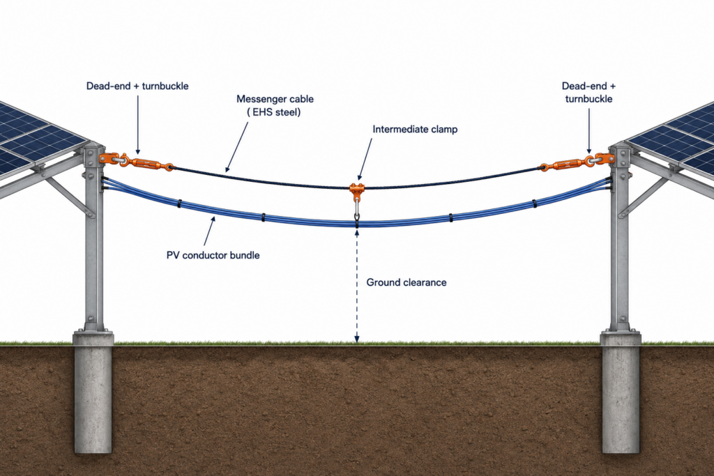
A typical run consists of:
- The messenger cable — usually 1/4 in or 3/8 in galvanized extra-high-strength (EHS) steel strand to ASTM A475, or aluminum-clad steel (“alumoweld”) and stainless where corrosion or galvanic compatibility govern.
- Dead-end terminations — a thimble plus a bolted or wedge-type clamp at each end, delivering the full horizontal tension into the structure.
- Tensioning hardware — turnbuckles for final adjustment; a come-along during stringing.
- Intermediate supports — messenger clamps at each racking post the run passes.
- Conductor attachment — UV-stable cable ties (stainless steel is the durable choice), cable hangers, or lashing at a fixed pitch.
The Mechanics: Sag and Tension
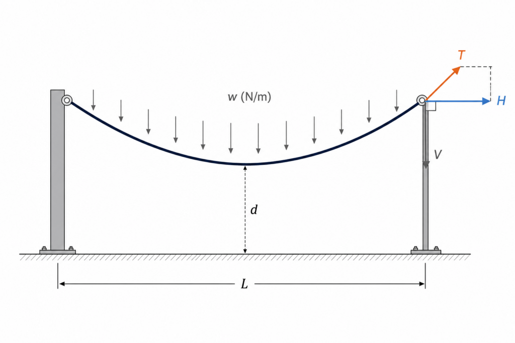
A flexible cable under a uniform load hangs as a catenary. The exact shape is a hyperbolic cosine, but for the shallow sags we use in solar runs — sag-to-span ratios of roughly 2 to 8 percent — the catenary is closely approximated by a parabola. The parabolic relationships are accurate to within a fraction of a percent in this range and far easier to apply on site.
With w = total weight per unit length of the suspended system, L = span, d = midspan sag, and H = horizontal tension component:
The intuition is worth holding onto: shallower sag means higher tension. The cable has to develop more horizontal pull to hold the same weight up over a flatter path. At an intermediate support the horizontal pulls from the two adjacent spans roughly cancel; at a dead-end, the full H is delivered into the end post as a sustained horizontal load. That dead-end value is the number to hand to the structural engineer.
Worked example — with assumptions stated
- Messenger: 1/4 in EHS steel strand ≈ 0.18 kg/m
- Conductor bundle: 12 × PV wire ≈ 0.06 kg/m each ≈ 0.72 kg/m
- Total suspended weight ≈ 0.90 kg/m → w ≈ 8.8 N/m, rounded to 9 N/m
- Load case: bare cable (no ice, no wind), level span, supports at equal elevation, ~20 °C
- Span L = 6 m (≈ 20 ft); target installation sag d = 0.30 m (5% of span)
V = (9)(6) ÷ 2 = 27 N
T = √1352 + 272 ≈ 138 N (≈ 31 lbf)
So at each dead-end the structure must resist about 135 N of horizontal pull in this benign installation condition. This is the bare-cable, fair-weather number — it is the floor, not the design value. The governing case is almost always cold weather with ice or wind, addressed next.
Ice, Wind, and Why the Cold Case Usually Wins
The messenger elongates as it warms and contracts as it cools. Sag grows in summer and shrinks in winter; tension does the reverse. A run strung tight on a hot afternoon can therefore overload its anchors on the first cold night. Glaze ice compounds this: it accretes radially on the cable and bundle, adding dead weight exactly when the conductor is already at its tightest.
Per ASCE 7, the added weight of a uniform radial ice layer of thickness t on a cylinder of bare diameter D is:
Two engineering realities matter more than the algebra. First, the relative impact is largest on thin members: a few millimetres of ice can rival or exceed the bare weight of a 1/4 in messenger, and the conductor bundle — with its much larger profile — accretes proportionally more. Second, ice rarely arrives alone; ASCE 7 pairs it with a concurrent wind that loads the now-enlarged profile transversely. In cold, exposed climates the combined cold-plus-ice-plus-wind case can drive the design tension to roughly two to three times the bare-cable value, and that multiplier should be confirmed by the site-specific load combination rather than assumed.
Set sag to temperature, not by feel
The practical consequence is simple: set sag, not tension, in the field, and reference it to the measured ambient temperature. Build a short stringing table giving the target midspan sag at, say, 5 °C increments. The installer matches the sag to the temperature at the moment of the pull, and the design tension is then implicitly correct across the full operating range. “Tight enough” is not a specification.
The conductors are a separate matter. Copper and aluminium have larger thermal-expansion coefficients than steel, but because they hang from the messenger rather than carrying tension, they only need somewhere to go. Leave a gentle slack loop between tie points so the conductors can move with temperature without straining their attachments or chafing at the supports. Lashing the conductors dead-straight is a common and avoidable error.
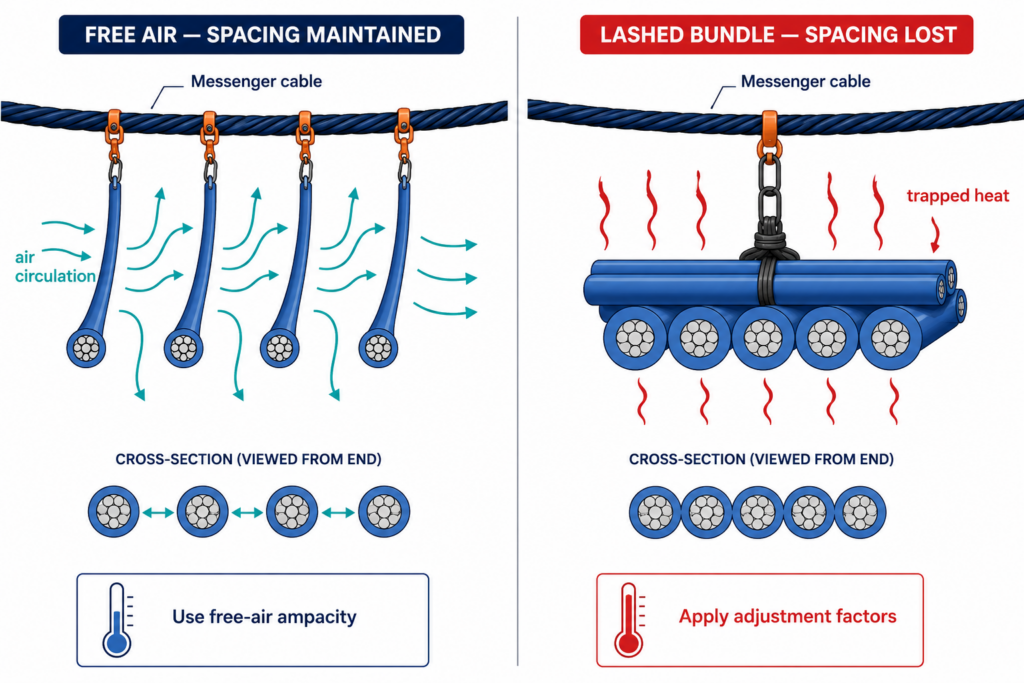
Ampacity: Free Air Is a Privilege, Not a Default
Messenger-supported conductors run in open air, which is electrically favourable. NEC 396.80 assigns them the free-air ampacities of Tables 310.17/310.18 — higher than the same conductors in conduit — provided they actually behave as free-air conductors. That qualifier is where designs go wrong.
“Free air” assumes air can circulate around each conductor. Lash a dozen conductors into a tight bundle against the messenger and you have, thermally, a cable bundle — not spaced free-air conductors. At that point the single-conductor free-air ampacity no longer applies cleanly, and the conductor-adjustment factors of NEC 310.15(C)(1) for more than three current-carrying conductors come into play:
| Current-carrying conductors | NEC 310.15(C)(1) adjustment |
|---|---|
| 4 – 6 | 80% |
| 7 – 9 | 70% |
| 10 – 20 | 50% |
| 21 – 30 | 45% |
| 31 – 40 | 40% |
| 41 and above | 35% |
Adjustment applies above three current-carrying conductors; spatial-diversity exceptions in 310.15(C)(1) can relieve it where bundles are short or separated.
Two corrections apply outdoors in every case. Ambient temperature — use the site ambient with the NEC 310.15(B) correction against the conductor’s insulation rating, not the 30 °C table baseline. Solar heating — conductors in direct sun run hotter than the surrounding air, so include a solar adder in the ambient. For PV source and output circuits, also remember the continuous-current sizing of NEC 690.8: the conductor must carry 125% of the 125%-adjusted short-circuit current (an effective 156% factor) before the ampacity corrections above are applied.
Finally, specify conductors listed for the exposure: sunlight-resistant PV Wire (UL 4703) or USE-2 (UL 854), per NEC 690.31(C). Standard building wire is not rated for unprotected outdoor sunlight and has no business in a messenger run.
Code, Clearance, Bonding, and Corrosion
Beyond ampacity, two requirements shape the layout. Mechanical support and protection: the messenger must be strong enough to support its conductors under all expected loads, and the conductors must not be installed where exposed to severe physical damage — which in a solar field means routing clear of vehicle paths and keeping room for vegetation management. Ground clearance: keep the lowest point of the sagging bundle above grade with margin for snow, ponding, and mowing equipment. Remember that clearance is governed by maximum sag — the hot-day, end-of-life condition — not the day you strung it.
Bonding the messenger (code-dependent)
A bare metallic messenger that could contact an energized conductor after an insulation failure becomes a shock and fault-current path. Whether bonding is mandatory depends on the construction and the jurisdiction: under NEC 250, metal parts likely to become energized must be bonded, and a metallic messenger can fall under that requirement — but it is not automatically a designated equipment-grounding conductor, and the AHJ’s interpretation governs. Confirm the obligation against NEC 250.110/250.116 and the local authority; where the messenger could become energized, bond it. As defensive practice on outdoor metallic strand, bonding it regardless is cheap insurance.
Avoid galvanic pairs
Galvanized steel strand, aluminium conductors, aluminium racking, and stainless ties share a wet outdoor environment for decades. Mismatched metals in direct contact corrode at the anodic member. The reliable combinations are stainless ties on a galvanized or alumoweld messenger, and listed bimetallic or stainless hardware wherever steel meets aluminium. The single most common premature failure is cheap cable ties that are not genuinely UV-stabilized — they embrittle and release the bundle within a few summers.
Engineering Notes and Common Mistakes
- Coordinate tension with the structural engineer early. The horizontal dead-end load is a real input to pile and racking design; discovering it after the foundations are set is expensive.
- String to a sag target, not a felt tension. Key the target to temperature with a stringing table.
- Mind the spans you cannot see. Unequal adjacent spans unbalance the horizontal pulls at an intermediate support and can drag clamps along the messenger. Keep spans uniform or use proper suspension hardware.
- Protect conductors at every crossing. Add edge protection anywhere the bundle passes a sharp racking edge — wind-induced motion abrades unprotected insulation over time.
- Never let the messenger become a tightrope for conductors. Conductors follow the cable with slack; they do not share its tension.
- Check ampacity against the as-built condition, not the most favourable table. The bundle you lash in the field is the bundle the calculation has to match.
The Bottom Line
A messenger run looks like trivial hardware, but it is the point where mechanical and electrical design meet, and it carries loads — tension into the structure, current into open air — that both disciplines must sign off on. Get the sag-tension right at the governing load case and the racking will not be surprised. Respect the free-air ampacity rules and the conductors will run cool enough to reach their service life. Bond the cable where code requires and match the metals, and the system will still be intact in thirty years. The whole problem reduces to a one-line tension calculation and a short list of deliberate hardware decisions — treat it that way, and the messenger system stops being a source of callbacks and becomes the cheapest reliable conductor management on the site.