Key Takeaways
- The per-unit (pu) system expresses every electrical quantity as a fraction of a chosen base, turning volts, amps, and ohms into dimensionless numbers that cluster near 1.0.
- You choose only two bases – apparent power (Sbase) and voltage (Vbase) – and base current and base impedance are then fixed by definition.
- Its defining payoff: when voltage bases track the transformer turns ratios, those ratios cancel, and a multi-voltage network collapses into one transformer-free reference frame.
- A quieter benefit is numerical conditioning – keeping every quantity near unity well-scales the matrices that load-flow and fault solvers must invert.
- Most per-unit errors are not conceptual. They come from sloppy base conversion, mixed single-phase and three-phase quantities, or off-nominal transformer taps.
Introduction
Open any short-circuit or load-flow case in PSS/E, ETAP, or PowerWorld, and the same pattern jumps out: bus voltages, line flows, and machine reactances reported not in kV and MW but as dimensionless numbers hovering around 1.0. That is the per-unit (pu) system at work. It is one of the first conventions a power engineer internalizes, and one of the easiest to apply carelessly – precisely because every per-unit number looks plausible whether or not the bases behind it are consistent.
This explainer is written for engineers who read per-unit results daily but want a firmer grip on the mechanics, especially the base-conversion step where most mistakes hide. We will cover the problem per-unit solves, how to build a consistent base, where the convention shows up in real studies, and the trade-offs worth respecting. The aim is not to relearn arithmetic you already know, but to sharpen the judgment that keeps the arithmetic honest.
The Problem This Solves
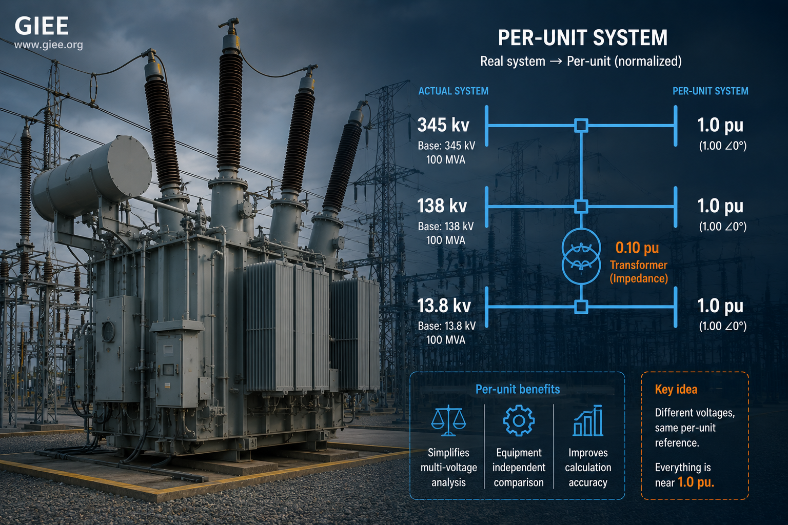
A realistic power system spans several voltage levels – say 345 kV transmission, 138 kV sub-transmission, and 13.8 kV distribution – stitched together by transformers. Work in actual units and every transformer forces you to refer impedances across its turns ratio, and that ratio enters as a square. Trace a fault current through three transformers in series and the bookkeeping alone invites arithmetic errors that no quick sanity check will catch.
The per-unit system removes that friction by normalizing each quantity to a base chosen for its location in the network. Done correctly, the transformer turns ratio cancels: a transformer’s series impedance becomes the same per-unit value whether you view it from the high side or the low side. The 345 kV and 13.8 kV portions of the network suddenly share one numerical frame, and impedances add in series or combine in parallel as if the transformers were not there at all.
There is a second, quieter benefit: per-unit values carry built-in engineering judgment. A bus at 0.94 pu is obviously low. A 0.10 pu transformer impedance is unremarkable. A 4.5 pu fault current is a familiar magnitude. The numbers themselves tell you whether a result is sane – something raw ohms and amps rarely do when read across mixed voltage levels.
A third benefit is purely numerical, and easy to overlook. Expressing every quantity near unity keeps the entries of the admittance and impedance matrices within a few orders of magnitude of one another. That improves the conditioning of the linear systems load-flow and fault solvers must invert, reducing round-off sensitivity in large cases – a practical reason the convention persists even where computers have made the hand-arithmetic argument moot.
![]()
How It Works
The entire system rests on a single definition.
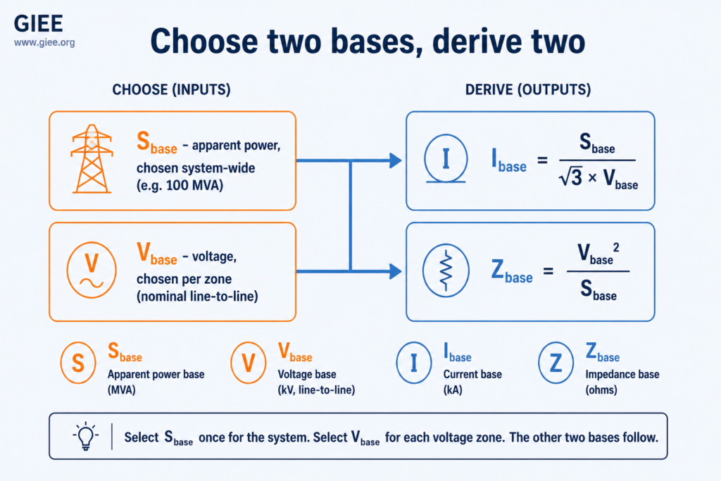
You choose only two bases; the other two follow. The conventional choice in system studies is a single, system-wide apparent-power base, Sbase (one number everywhere, almost always 100 MVA), and a voltage base, Vbase, set per zone to the nominal line-to-line voltage of that zone. The split is deliberate: Sbase is common to the whole network so that power balances cleanly across every transformer, while Vbase steps at each transformer so the voltage bases track the turns ratios. That second choice is exactly what makes the ratio cancel.
From those two, the current and impedance bases are fixed. For a three-phase system referenced to line-to-line voltage and three-phase apparent power:
Because two of the four bases are chosen and two are derived, it is worth keeping their roles straight in one place.
| Base quantity | Symbol | Status | How it is set |
|---|---|---|---|
| Apparent power | Sbase | Chosen (system-wide) | One value for the whole study, commonly 100 MVA |
| Voltage | Vbase | Chosen (per zone) | Nominal line-to-line voltage of each zone |
| Current | Ibase | Derived | Sbase / (√3 × Vbase) |
| Impedance | Zbase | Derived | Vbase² / Sbase |
With the framework set, a concrete base makes it tangible. Take Sbase = 100 MVA and Vbase = 138 kV on the sub-transmission zone, and put a line of 19 Ω series reactance into per-unit.
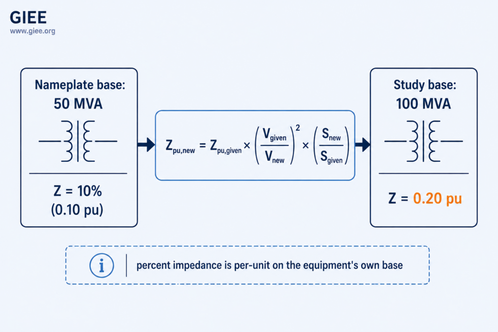
The step that genuinely trips people up is changing base. Equipment impedances are published on the manufacturer’s nameplate base – the device’s own MVA and voltage rating – which rarely matches your study base. The fix follows from a single fact: the physical impedance in ohms is fixed, so ZΩ = Zpu × Zbase must hold on both the nameplate base and the study base. Equating the two and rearranging gives the conversion below.
Read the structure, not just the formula. The voltage term is squared because impedance scales with voltage squared at fixed power; the power term is linear. When you set each zone’s Vbase to its nominal voltage – the normal practice – the nameplate and study voltage bases usually agree, the voltage term goes to 1, and only the MVA ratio remains.
Real-World Application
Per-unit is not an academic nicety. It is baked into how the industry specifies, exchanges, and analyzes equipment data.
Nameplate and percent impedance
Transformer and generator ratings list impedance as a percentage, and percent impedance is simply per-unit × 100 on the equipment’s own base. A “10% impedance” 138/13.8 kV transformer is telling you its series reactance is 0.10 pu, directly usable once converted to the study base. This convention – formalized in analysis guides such as IEEE Std 399 (the Brown Book) and in IEC 60909 for short-circuit calculation – lets engineers place a 5 MVA distribution transformer and a 500 MVA generator step-up unit on the same scale without first translating either to ohms.
Short-circuit studies
Fault analysis is where per-unit earns its keep. With every reactance referred to a common base, the fault level at a bus drops out of the Thevenin equivalent per-unit reactance almost by inspection: Fault MVA ≈ Sbase / Xpu. A bus seeing 0.05 pu source reactance on a 100 MVA base therefore carries roughly 2,000 MVA of fault duty – a one-line mental calculation that would be tedious to reach in ohms and amps. The same relationship runs in reverse for equipment ratings: a generator’s per-unit subtransient reactance maps directly to its short-circuit contribution, which is why machine data is exchanged in per-unit in the first place.
Voltage limits and protection
Operators and planners read bus voltages in per-unit against the limits in ANSI C84.1, and relay settings, power-flow reports, and stability studies all ride on the same normalized framework. The convention even threads into sequence-domain work: positive-, negative-, and zero-sequence networks are each built and combined in per-unit, though each carries its own base bookkeeping. For a deeper treatment of fault duty in distribution, see our guide to short-circuit analysis on distribution systems.
Limitations and Trade-offs
The per-unit system is robust, but it has sharp edges that reward respect.
The most common failure is base inconsistency – mixing values referred to different Sbase or Vbase choices inside one calculation. Because every per-unit number looks reasonable in isolation, the error rarely announces itself. It surfaces only as a fault current or voltage that is wrong by a clean integer ratio, which is exactly the kind of result that survives a casual review.
A close second is confusing single-phase and three-phase bases, or mixing line-to-line and line-to-neutral voltage. The formulas above assume line-to-line voltage with three-phase power; combine them with a per-phase quantity and a stray √3 sneaks in or drops out. (Notably, a properly built three-phase per-unit system and a per-phase line-to-neutral system yield the same per-unit numbers – which is convenient, but only if you do not straddle the two midway through a calculation.)
Finally, per-unit hides physical units, which is a feature until it isn’t. When you need to size a conductor, set a CT ratio, or specify a breaker interrupting rating, you must convert back to amps and ohms – and that round trip reintroduces the very base arithmetic per-unit was meant to suppress. The discipline that protects the forward direction protects the return trip too: know which base each number lives on before you leave the per-unit world.
Conclusion
The per-unit system is less a calculation trick than a coordinate change. Pick a sensible Sbase and a per-zone Vbase, derive current and impedance, and a multi-voltage network becomes a single, transformer-free reference frame whose numbers carry their own sanity check. The concept is simple; the engineering is in the base management. Lock your Sbase early, set voltage bases to track the turns ratios, convert nameplate impedances deliberately, keep three-phase and line-to-line conventions straight, and handle off-nominal taps explicitly – do that, and per-unit will do exactly what it was designed to do: make a complicated network easy to reason about, and easy to trust.