Key Takeaways
- Ampacity is a safety limit; voltage drop is a performance limit. One protects the cable from overheating, the other protects the load from poor voltage.
- They are confused because both scale with current and both are eased by a larger conductor, but they are governed by entirely different physics.
- Ampacity is set by heat balance and installation conditions; voltage drop is set by conductor impedance and circuit length.
- On long runs, voltage drop almost always governs the design – the cable is far larger than ampacity alone would require.
Conductor sizing is one of the most routine decisions an electrical engineer makes, and one of the most frequently misunderstood. Two limits sit behind every cable selection: ampacity and voltage drop. Both depend on the current the cable carries. Both are relieved by choosing a bigger conductor. And both are checked during design. Because they share these symptoms, they are often treated as a single problem, or worse, as interchangeable. They are not. As feeders get longer, loads get denser, and electrification pushes more current through distribution networks, the gap between these two limits is where good design is won or lost.
Two Limits, One Cable
The confusion is understandable. When an engineer increases conductor cross-section, both the temperature rise and the voltage drop improve at the same time. It is easy to conclude that they are two views of the same effect. They are not. Ampacity is a thermal question: how much current can the cable carry before its insulation overheats? Voltage drop is an electrical performance question: how much voltage is lost along the cable before it reaches the load?
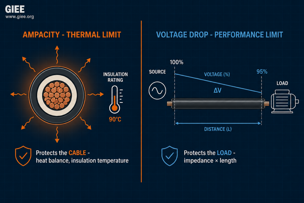
The cleanest way to separate them is to ask what each one protects. Ampacity protects the cable. Voltage drop protects the load. A circuit can comfortably satisfy one while badly failing the other, and that is exactly where designers get caught out.
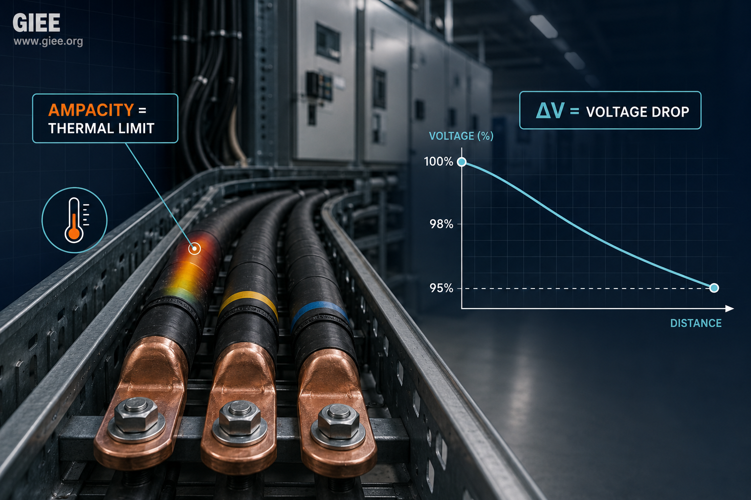
Ampacity: The Thermal Limit
Ampacity comes from a heat balance. Current flowing through a conductor generates heat in proportion to the square of the current and the conductor resistance. That heat must escape to the surroundings. When heat generated equals heat dissipated, the conductor settles at a steady temperature. Ampacity is simply the current at which that steady temperature reaches the insulation limit, for example 75 °C or 90 °C for common cross-linked polyethylene (XLPE) insulation.
Because ampacity is about heat, it depends heavily on the installation environment, not just the conductor itself. Ambient temperature, whether the cable is in free air or buried, soil thermal resistivity, grouping with other cables, and conduit fill all change how easily heat escapes. The same conductor can have very different ampacities in two different installations. This is why ampacity tables always carry correction and grouping factors. Exceed ampacity and the consequence is physical: accelerated insulation aging, loss of mechanical strength, and eventually thermal failure. It is fundamentally a safety and asset-protection limit.
Voltage Drop: The Performance Limit
Voltage drop is a different animal. As current travels along a conductor, the conductor impedance consumes part of the supply voltage, so the voltage available at the load is lower than the voltage at the source. Conceptually, the drop grows with the current, the circuit length, and the conductor impedance:
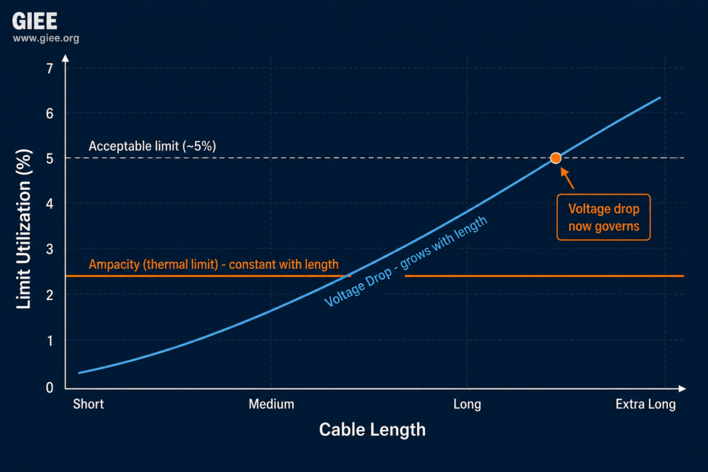
The critical term is length. Ampacity does not care how long the cable is – a conductor in steady state reaches the same temperature whether the run is 10 m or 500 m, because the heat balance is per unit length. Voltage drop scales directly with length. Double the run and you double the drop for the same current. This single fact is why the two limits diverge so sharply on real projects.
Voltage drop does not damage the cable. It degrades the load. Motors lose torque and run hotter, lighting dims, electronic power supplies work harder, and sensitive controls can misbehave. Most codes and standards therefore recommend keeping total voltage drop within roughly 3 percent to 5 percent from source to load, depending on the circuit type. It is a quality-of-supply and efficiency limit, not a safety limit.
Why One Almost Never Equals the Other
Here is the practical heart of the matter. A cable selected purely to satisfy ampacity will often fail voltage drop on a long run, while a cable selected for voltage drop on a long run is usually far larger than ampacity alone would demand. The two limits rarely land on the same conductor size.
Consider a feeder thermally rated to carry, say, 200 A. Supplying a 150 A load over a 20 m run, that conductor is perfectly fine on both counts – it runs cool and the voltage at the load is well within limits. Take the identical conductor and the identical load, but stretch the run to 250 m, and the thermal picture has not changed at all. The cable still carries 150 A and still runs at the same temperature. Voltage drop, however, has grown more than tenfold with the distance, and may now sit well beyond an acceptable 5 percent. The engineer must increase the conductor size, not because the cable is in any danger of overheating, but to deliver usable voltage to the load.
This is the insight that the ampacity-equals-voltage-drop reflex misses: on short runs ampacity tends to govern, and on long runs voltage drop tends to govern. The crossover depends on system voltage too. Low-voltage circuits suffer voltage drop badly because the percentage drop is large relative to a small nominal voltage, which is one reason medium-voltage distribution is preferred for moving power over distance.
Ampacity vs Voltage Drop at a Glance
| Aspect | Ampacity | Voltage Drop |
|---|---|---|
| Governing physics | Heat balance (thermal) | Conductor impedance (electrical) |
| What it protects | The cable and its insulation | The load and supply quality |
| Type of limit | Safety / asset protection | Performance / efficiency |
| Depends on length? | No | Yes, directly |
| Strongly affected by | Ambient, grouping, install method | Length, current, system voltage |
| Failure consequence | Insulation aging, thermal failure | Weak voltage, poor load operation |
| Tends to govern when | Runs are short, currents are high | Runs are long, voltage is low |
Where Each Governs in Practice
The two limits show up differently across the kinds of work GIEE readers do every day. In dense building services and switchgear connections, where runs are short and currents are large, ampacity and the associated grouping and thermal derating usually drive the conductor choice. In long outdoor feeders, rural distribution, large solar farms with collector circuits spanning hundreds of metres, and electric-vehicle charging hubs at the end of long supply runs, voltage drop typically takes over and forces a conductor well beyond the thermal minimum.
Renewable and distributed-energy projects make the distinction sharper still. A photovoltaic array spread across a wide site pushes generated current back over long collector runs, and the cumulative voltage rise or drop along those runs can become the binding constraint long before any cable approaches its thermal rating. The disciplined engineer checks both limits independently, every time, and sizes the conductor to whichever one is more demanding for that specific circuit – rather than assuming the two will agree.
Conclusion
Ampacity and voltage drop look alike because both respond to current and both yield to a bigger conductor, but they answer two different questions. Ampacity asks whether the cable can survive the heat; voltage drop asks whether the load receives usable voltage. One is a safety limit tied to the installation environment, the other a performance limit tied to circuit length. Keep them separate in your thinking, check each on its own terms, and the conductor you choose will be both safe and effective.
To go deeper into conductor selection, derating, and power-system fundamentals, explore the GIEE course catalogue and our related guides on distribution design and power quality.