Key Takeaways
- Voltage drop and poor power factor share a root cause – reactive current drawn by inductive load – but they are distinct problems that respond to different equipment.
- Shunt capacitor banks supply reactive power locally, cutting line current, I²R losses, and the reactive share of voltage drop.
- Voltage regulators actively hold voltage to a setpoint along the feeder, correcting the resistive (real-power) drop that capacitors cannot.
- Capacitors shrink the problem; regulators manage what remains. Run together, the regulator works less, lasts longer, and the whole feeder runs at lower loss.
- Coordinating switched capacitors with regulators through Volt/VAR control keeps the two devices from fighting each other.
Electrification of heat and transport, data center build-out, and the return of energy-intensive manufacturing are pushing more current down conductors that were sized decades ago. Two symptoms tend to surface together: voltage at the far end of a feeder sags below limits, and the power factor seen at the substation drifts down as inductive load climbs. Engineers reach for one of two tools – a capacitor bank or a voltage regulator – and often assume that fixing one symptom fixes the other. It usually does not.
This article is for distribution and plant engineers who need to decide what a feeder actually requires. We will look at what each device does physically, where each one falls short on its own, and three concrete scenarios – drawn from industrial plants, long distribution feeders, and motor-heavy systems – that map to real installations.
Two Problems, One Root Cause
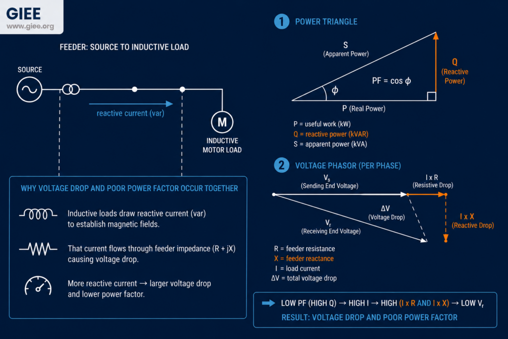
Most distribution loads are inductive. Induction motors, transformers, and lightly loaded lines all draw reactive power (measured in var) in addition to the real power (watts) that does useful work. Reactive power does not perform work, but it still flows as current through every conductor, transformer, and breaker between the source and the load.
That single flow of reactive current creates two separate headaches. First, it drags down the power factor (PF) – the ratio of real power to apparent power, equal to cosφ. A plant pulling 500 kW at 0.80 PF is actually loading the system to 625 kVA. Second, the same reactive current drops voltage as it passes through line reactance. The standard approximation makes the link explicit.
Equation 1 carries the whole argument of this article. Voltage drop has two terms: a resistive term driven by real power (P · R) and a reactive term driven by reactive power (Q · X). Poor power factor is really a statement about the Q in that equation. So fixing power factor attacks only one of the two voltage-drop terms – and does nothing at all for the resistive term that dominates on long, high-resistance lines.
Why Solving One Problem Is Not Enough
Because the two symptoms share a cause, it is tempting to assume one fix clears both. In practice each device leaves a gap that the other is built to close.
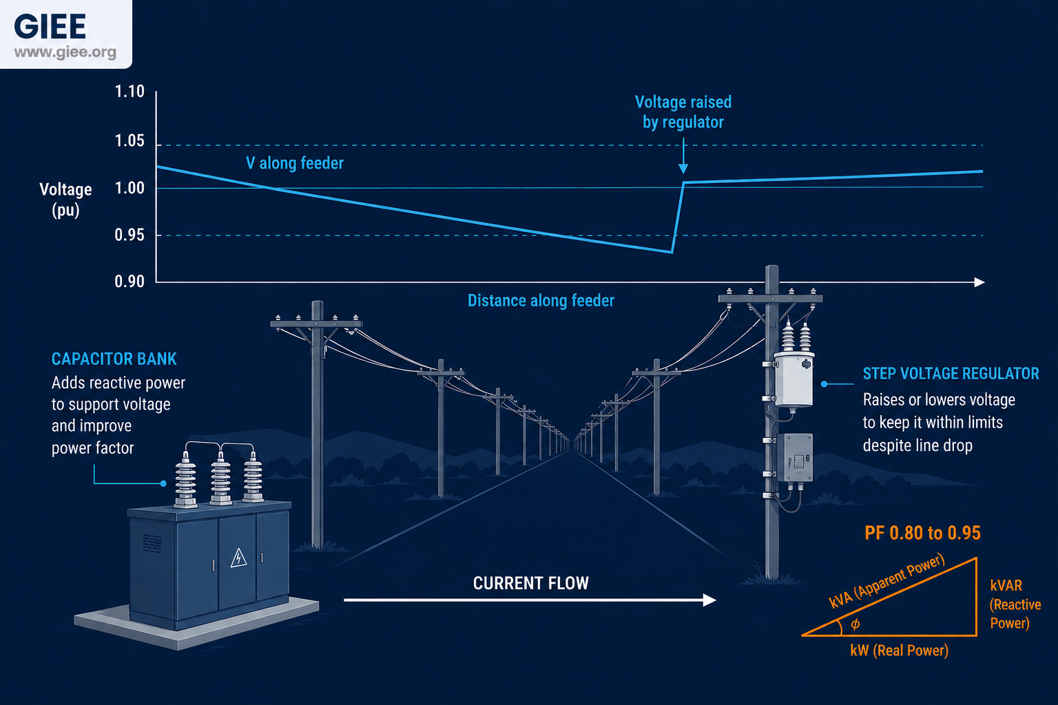
A capacitor bank cuts reactive current, so it shrinks the Q · X term and lifts voltage somewhat. But it does nothing about the P · R term. On a long rural feeder carrying real power over high-resistance conductor, the resistive drop can dominate, and a feeder can still sag below limits even after the power factor is corrected to unity. Capacitors also provide fixed or stepped support rather than regulation to a target, and because their var output scales with the square of voltage, they deliver the least support exactly when voltage is already low.
A voltage regulator solves the opposite half. It holds voltage to a setpoint regardless of which term is causing the drop, which makes it the right tool for resistive sag and for load that swings through the day. What it does not do is reduce current or losses. A regulator at the substation leaves the reactive current flowing through the entire feeder downstream, so the power factor stays poor and the I²R losses stay high. It treats the symptom without touching the cause.
What Capacitor Banks Actually Do
A shunt capacitor bank is a local source of reactive power. Installed near the load, it supplies the var the load demands so that reactive power no longer has to be imported all the way from the source. The effect cascades through everything upstream: the same real power now flows at lower apparent power, which means lower current.
Lower current is where the value compounds. Conductor and transformer losses scale with the square of current, so even a modest current reduction produces an outsized loss reduction. Correcting power factor also frees up apparent-power capacity in transformers and lines, often deferring a costly upgrade, and it removes utility power-factor penalties for industrial customers. The worked example shows the magnitudes.
What Voltage Regulators Actually Do
A voltage regulator holds voltage where you want it. The two common forms are the load tap changer (LTC) built into a substation transformer and the step voltage regulator – an autotransformer with a tap changer – placed at the substation or out on the line. Most step regulators provide a range of plus or minus 10% in 32 steps of 0.625% each, switching taps automatically as load and voltage move through the day.
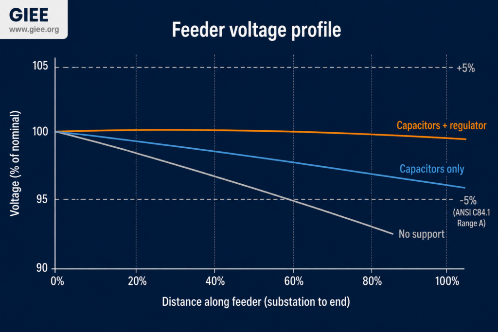
The feature that makes regulators indispensable is line drop compensation (LDC). By dialing in the R and X of the line ahead of it and measuring the current passing through, the regulator estimates the voltage at a remote load center and boosts just enough to hold that point in band, not the point where the regulator sits. This is how a single regulator can keep an entire downstream section inside ANSI C84.1 Range A – roughly 114 to 126 V on a 120 V base – even as the load profile changes.
What the regulator does not change is the current flowing through the feeder or the power factor of the load. It manages the consequence (voltage) rather than the cause (reactive flow). Held voltage with poor power factor still means high losses everywhere upstream of the load.
How the Two Complement Each Other
Put the two devices on the same feeder and their strengths line up against each other’s weaknesses. Capacitors remove reactive current, which shrinks both the Q · X voltage drop and the I²R losses across the whole system. That leaves the regulator with a smaller, mostly resistive drop to manage and a load that swings less in apparent power. The regulator, in turn, handles the part capacitors can never reach: the real-power resistive drop and the dynamic, time-of-day variation that fixed capacitors cannot track.
The operational benefits are concrete. With capacitors carrying the reactive burden, the regulator runs nearer the center of its tap range, so it has more headroom for load swings and makes fewer tap operations, which directly extends the life of the tap changer. Meanwhile the whole feeder operates at higher power factor and lower loss. The capacitor handles steady reactive demand cheaply; the regulator handles precision and dynamics. Neither replaces the other.
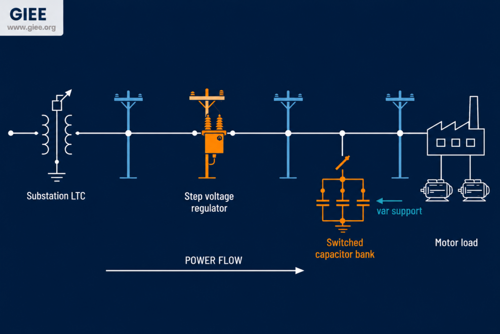
The one caution is coordination. Switched capacitors change the feeder voltage when they energize, and a regulator set to chase voltage can respond by stepping its taps, which then changes the picture the capacitor controller sees. Left uncoordinated, the two can hunt against each other. Modern Volt/VAR control (VVC), increasingly delivered through an advanced distribution management system, sequences capacitor switching and regulator tap moves so they reinforce rather than fight.
| Attribute | Capacitor Bank | Voltage Regulator |
|---|---|---|
| Primary function | Supply reactive power (var) locally | Hold voltage to a setpoint |
| Effect on power factor | Improves it directly | No direct effect |
| Effect on line current and losses | Reduces both (losses scale with I²) | Little to none |
| Effect on voltage | Modest rise; output falls as V² | Direct, controlled boost or buck |
| Corrects resistive (P · R) drop? | No | Yes |
| Control type | Fixed or switched in steps | Continuous tap regulation with LDC |
| Main light-load risk | Overvoltage if left switched in | Excess tap operations / hunting |
| Typical standard | IEEE Std 1036 | IEEE C57.15, ANSI C84.1 |
Three Scenarios From the Field
When capacitor banks alone are enough
Consider an industrial plant running banks of large induction motors a short distance from a stiff substation. Voltage at the plant is comfortably in band, but the metered power factor sits at 0.78 and the utility is billing a power-factor penalty every month. Here the problem is purely reactive, and the supply is strong enough that voltage was never at risk. Power-factor correction capacitors at the plant – often switched in stages or controlled per motor – restore the power factor, cut the demand charge, reduce current through the service, and unmask transformer capacity. No regulator is needed because nothing was wrong with the voltage.
When a voltage regulator is required
Now take a long rural distribution feeder serving scattered farms and a small town at its end. The load is fairly ordinary in power factor, but the feeder runs many kilometers over relatively small conductor, so resistance is high and the dominant voltage drop is the P · R term. By midday peak, the end-of-line voltage dips below the lower ANSI limit. Capacitors would barely help here – the drop is resistive, not reactive – and could push voltage high during the light-load overnight period. A line voltage regulator with line drop compensation, or an LTC at the substation tuned to the load center, is the correct tool. It tracks the load through the day and keeps the far end in band.
When both must be used together
The combined case is the most common on real feeders. Picture a long feeder that terminates in an industrial park full of large motors, or a rural circuit feeding heavy agricultural pumping load. Both symptoms are present at once: the inductive load pulls the power factor down and inflates losses, while the length of the line produces a resistive voltage drop that capacitors cannot reach. Here the two devices divide the work cleanly. Capacitors at or near the load slash the reactive current, recover the I²R losses, and take a bite out of the reactive share of the voltage drop. The regulator then trims the remaining resistive and dynamic variation to hold the far end in band. As a bonus, with the capacitors carrying the var, the regulator steps less often and lasts longer. Large-motor starting adds one more wrinkle: the inrush causes a momentary deep voltage dip, and while neither device fully solves starting transients, a stiffer feeder – higher power factor and tighter voltage – rides through them better.
Conclusion
Capacitor banks and voltage regulators are not competing answers to the same question. Equation 1 makes the division of labor unavoidable: capacitors attack the reactive cause – cutting var, current, and losses – while regulators manage the voltage result, including the resistive drop that capacitors cannot touch. Decide which one a feeder needs by decomposing its voltage drop and checking its power factor, not by reaching for whichever device is on the truck. On short, stiff systems with a power-factor problem, capacitors alone will do. On long, resistive feeders with a voltage problem, a regulator is the tool. And on the long, motor-heavy feeders that describe a large share of real networks, you will want both, coordinated through Volt/VAR control so they reinforce each other. Start your next study by separating the two drop terms – the right hardware choice usually falls out of the numbers.