Key Takeaways
- Faults divide into two families: symmetrical (balanced three-phase) and asymmetrical (single line-to-ground, line-to-line, and double line-to-ground).
- Single line-to-ground (SLG) faults are by far the most common; three-phase faults are the rarest but usually impose the most severe duty.
- Symmetrical faults are solved with a single-phase positive-sequence model; asymmetrical faults require symmetrical components, the positive-, negative-, and zero-sequence networks.
- The symmetrical (AC) magnitude sets relay pickup and equipment ratings; the X/R ratio sets the DC offset, the peak current, and the breaker’s making and asymmetrical interrupting duty.
- IEC 60909 and IEEE Std 399 (the Brown Book) define the standard calculation methods; inverter-based resources require modeling assumptions different from synchronous machines.
Why Fault Analysis Drives Every Study
Every interconnection study, protection coordination review, and equipment specification rests on one number: the available fault current at a bus. Underestimate it and you under-rate a breaker that then fails to interrupt during an actual fault. Overestimate it and you over-specify switchgear and mis-coordinate protection.
This explainer is written for working power engineers who need a precise mental model of the fault types, the frequency with which each occurs, and the analysis method that applies to each. The mathematics is kept to the forms used in practice rather than full derivations, which are available in standard power systems texts.
What a Fault Is
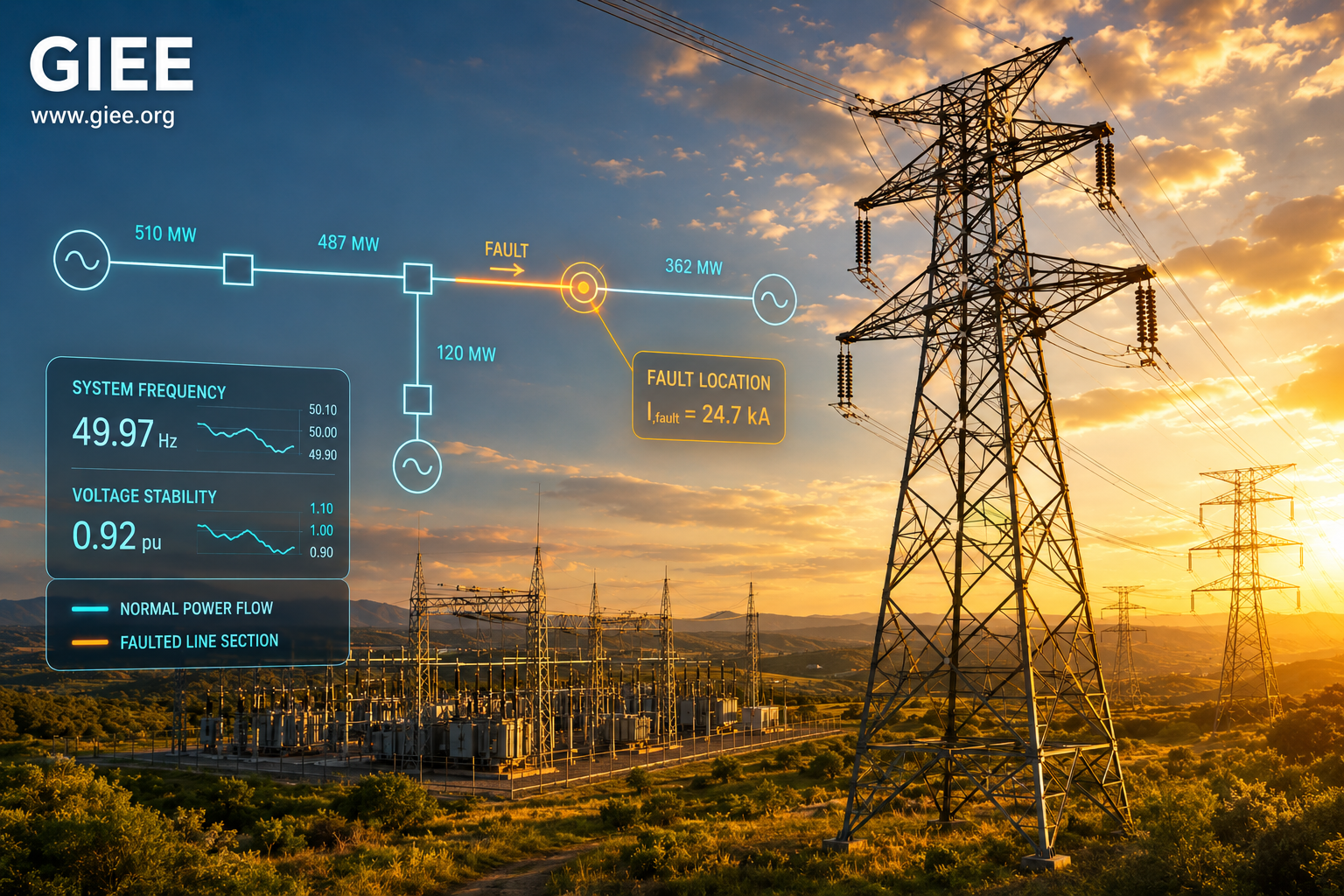
A fault is an abnormal connection in the power system that diverts current along an unintended path, most often a short circuit between conductors, or between a conductor and ground. When the high series impedance of a load is replaced by the very low impedance of a short circuit, current rises sharply, reaching tens of kiloamperes (kA) at a strong transmission bus.
That current is damaging in three ways at once. It heats conductors and equipment toward their thermal limits, it imposes large mechanical forces on busbars and transformer windings, and it depresses voltage across the surrounding network. Protection systems exist to detect the fault and clear it, typically within a few cycles, before the damage compounds. Setting that protection correctly requires knowing the fault current for each fault type.
The causes are predominantly physical: insulation breakdown from ageing or overvoltage, lightning strikes on overhead lines, equipment failure, vegetation or wildlife contact, insulator contamination, and human error during switching. The cause largely governs how often a fault occurs; the type governs the analysis method.
Fault Classification
Faults divide cleanly into two families according to whether they leave the three phases balanced.
Symmetrical (balanced) faults
A symmetrical fault affects all three phases equally. Its two members are the three-phase fault (LLL) and the three-phase-to-ground fault (LLLG). Because the system stays balanced, it can be analysed with a single-phase equivalent using the positive-sequence network alone. For a bolted three-phase fault at a bus:
I_f = E / Z1

where:
  E  = pre-fault phase (line-to-neutral) voltage
  Z1 = positive-sequence Thevenin impedance at the bus
In per-unit on a chosen base, the pre-fault voltage is normally taken as E = 1.0 pu, so I_f = 1 / Z1 pu. Symmetrical faults are uncommon, commonly cited in protection literature as roughly 5% of all faults, but they typically produce the highest current, which is why they generally set the interrupting rating of circuit breakers.
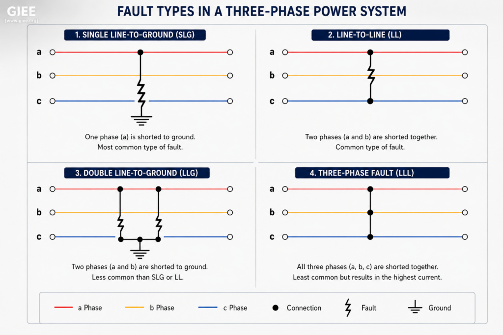
Asymmetrical (unbalanced) faults
An asymmetrical fault leaves the three phases unbalanced, so a single-phase model no longer applies. There are three types:
| Fault type | Phases involved | Typical share |
|---|---|---|
| Single line-to-ground (SLG) | One phase to ground | 70-80% |
| Line-to-line (LL) | Two phases together | ~15% |
| Double line-to-ground (LLG) | Two phases to ground | ~10% |
These proportions are approximate figures widely reported in protection literature and vary with system design and environment; verify them against the system under study. The SLG fault dominates because lightning, insulator flashover, and conductor-to-ground contact are the most frequent fault mechanisms on overhead systems.
Symmetrical Components
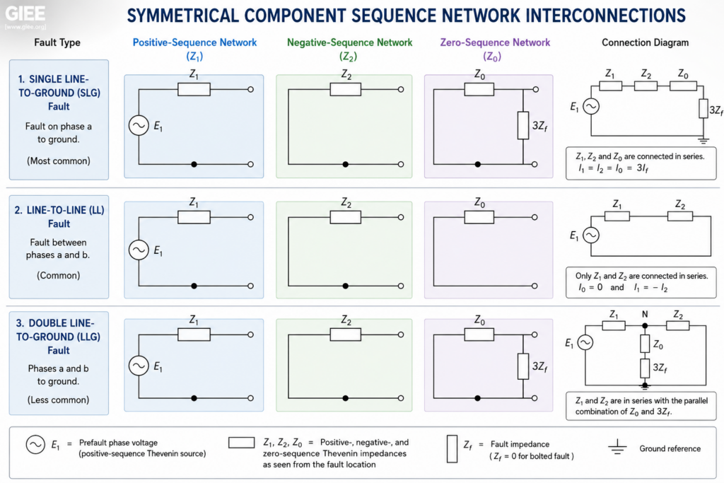
Charles Fortescue showed that any set of three unbalanced phasors can be resolved into three balanced sets: a positive-sequence set (normal phase rotation), a negative-sequence set (reverse rotation), and a zero-sequence set (three in-phase quantities). Each sequence has its own network and Thevenin impedance, Z1, Z2, and Z0, and each fault type interconnects those networks in a specific configuration.
For a bolted SLG fault on phase a, the three sequence networks connect in series:
I_a = 3 * E / (Z1 + Z2 + Z0)

For a fault with arc/ground resistance Zf, add 3 * Zf to the denominator:
I_a = 3 * E / (Z1 + Z2 + Z0 + 3*Zf)
For a bolted line-to-line fault between two phases, only the positive- and negative-sequence networks participate, because with no ground path the zero-sequence network is absent. They connect so that the source drives current through Z1 and Z2 in series. The sequence current and the resulting line current in the two faulted phases are:
I_a1 = E / (Z1 + Z2)

I_f  = sqrt(3) * E / (Z1 + Z2)        (line current in the faulted phases)
The zero-sequence path is what distinguishes ground faults. Z0 depends strongly on transformer winding connections, a delta winding blocks zero-sequence current and so does not appear in the zero-sequence network seen from the delta side, and on whether and how the system neutral is grounded (solidly, through an impedance, or ungrounded). A change as ordinary as a different transformer vector group can therefore shift the available ground-fault current substantially.
This also explains how SLG and three-phase currents compare. Using the common approximation Z2 approx Z1, the SLG current equals the three-phase current when Z0 = Z1, falls below it when Z0 > Z1 (the usual case on distribution feeders), and can exceed it when Z0 < Z1, as occurs close to a solidly grounded transformer or generator neutral. Both faults must therefore be calculated; neither can be assumed to bound the other.
Fault Current in Practice
In practice, sequence networks are rarely solved by hand for a full system. Tools such as ETAP, PSS/E, PowerWorld, and OpenDSS assemble the sequence impedance matrices from the network model and report fault current and voltage at every bus for each fault type. IEC 60909 defines the standardised calculation method most studies follow: it represents the source as an equivalent voltage c * Un / sqrt(3) at the fault location, where Un is the nominal line-to-line voltage and the voltage factor c (for example, c_max = 1.1 above 1 kV) accounts for pre-fault loading and tap variation. IEEE Std 399 (the Brown Book) provides the parallel guidance for industrial systems in North American practice.
Worked example: three-phase bolted fault
Assumptions
- Three-phase bolted fault at a 13.8 kV bus
- Positive-sequence Thevenin impedance Z1 = 0.05 pu on a 100 MVA, 13.8 kV base
- Pre-fault voltage E = 1.0 pu (line-to-neutral)
Base current:
I_base = S_base / (sqrt(3) * Un)
       = 100 MVA / (sqrt(3) * 13.8 kV)
       = approx 4,184 A

Fault current:
I_f = E / Z1 = 1.0 / 0.05 = 20 pu
    = 20 * 4,184 A
    = approx 84 kA
Equivalently, the short-circuit level is S_base / Z1 = 2,000 MVA. This is a comparatively stiff bus; weaker distribution buses commonly see 10-25 kA. The breaker must interrupt this symmetrical current with margin, and, as shown next, its peak and asymmetrical duty depend on the X/R ratio.
Why X/R ratio matters
The equations above give the symmetrical (AC) fault-current magnitude. The instantaneous peak current, which sets a breaker’s making (close-and-latch) duty and the mechanical forces on equipment, also depends on the decaying DC offset, governed by the X/R ratio at the fault point. IEC 60909 expresses the peak as:
i_p   = kappa * sqrt(2) * I_k

kappa = 1.02 + 0.98 * e^(-3*R/X)

where:
  I_k   = initial symmetrical short-circuit current
  kappa = peak (asymmetry) factor
As X/R rises, near large generators and transformers, kappa approaches its limit, the DC component decays more slowly, and both the peak and the asymmetrical interrupting duty increase. Reporting only the symmetrical RMS value understates what the breaker must withstand. These fault figures also feed directly into arc-flash incident-energy calculations and protection coordination.
Where Classical Models Break Down
Three issues commonly undermine otherwise careful studies.
Fault resistance. The bolted-fault equations assume zero fault impedance. Real ground faults often include significant arc and ground resistance, which reduces the current and can leave a sensitive ground relay unable to detect a high-impedance fault. The 3*Zf term must be carried where high-impedance faults are a concern.
Inverter-based resources. Inverter-based resources (IBR) do not behave like synchronous machines under fault. A synchronous generator delivers several times its rated current into a nearby fault; an inverter is current-limited by its semiconductors and control firmware, typically to about 1.1-1.2 times rated current. A grid-following inverter behaves as a controlled current source that injects a regulated (often largely reactive) current during a voltage dip, while a grid-forming inverter presents a controlled voltage behind a virtual impedance but remains hardware current-limited. Representing either as a fixed voltage behind a sub-transient impedance overstates its contribution and misrepresents the fault-current angle.
At high IBR penetration the aggregate fault level falls and the negative-sequence content changes, which can desensitise conventional overcurrent and directional protection. This is a growing reason to revisit the assumptions built into classical fault studies and, increasingly, to use electromagnetic-transient (EMT) models for IBR-dominated networks.
Series (open-circuit) faults. A broken conductor or open phase is not a short circuit, but it still produces damaging unbalance and negative-sequence current that is particularly harmful to motors and generators. Because standard fault studies focus on shunt faults, series faults are easy to overlook.
Conclusion
Classify the fault first, then choose the method: symmetrical faults are solved with a single positive-sequence model, while every unbalanced fault requires the three sequence networks connected in the configuration that matches the fault type. The SLG fault is the one most frequently encountered; the three-phase fault usually rates the equipment; and the X/R ratio determines the peak and asymmetrical duty the equipment must survive. Calculate both fault types, build the zero-sequence network honestly, and account for the falling, current-limited contribution of inverter-based resources, and the resulting protection settings and equipment ratings will rest on solid ground.