Key Takeaways
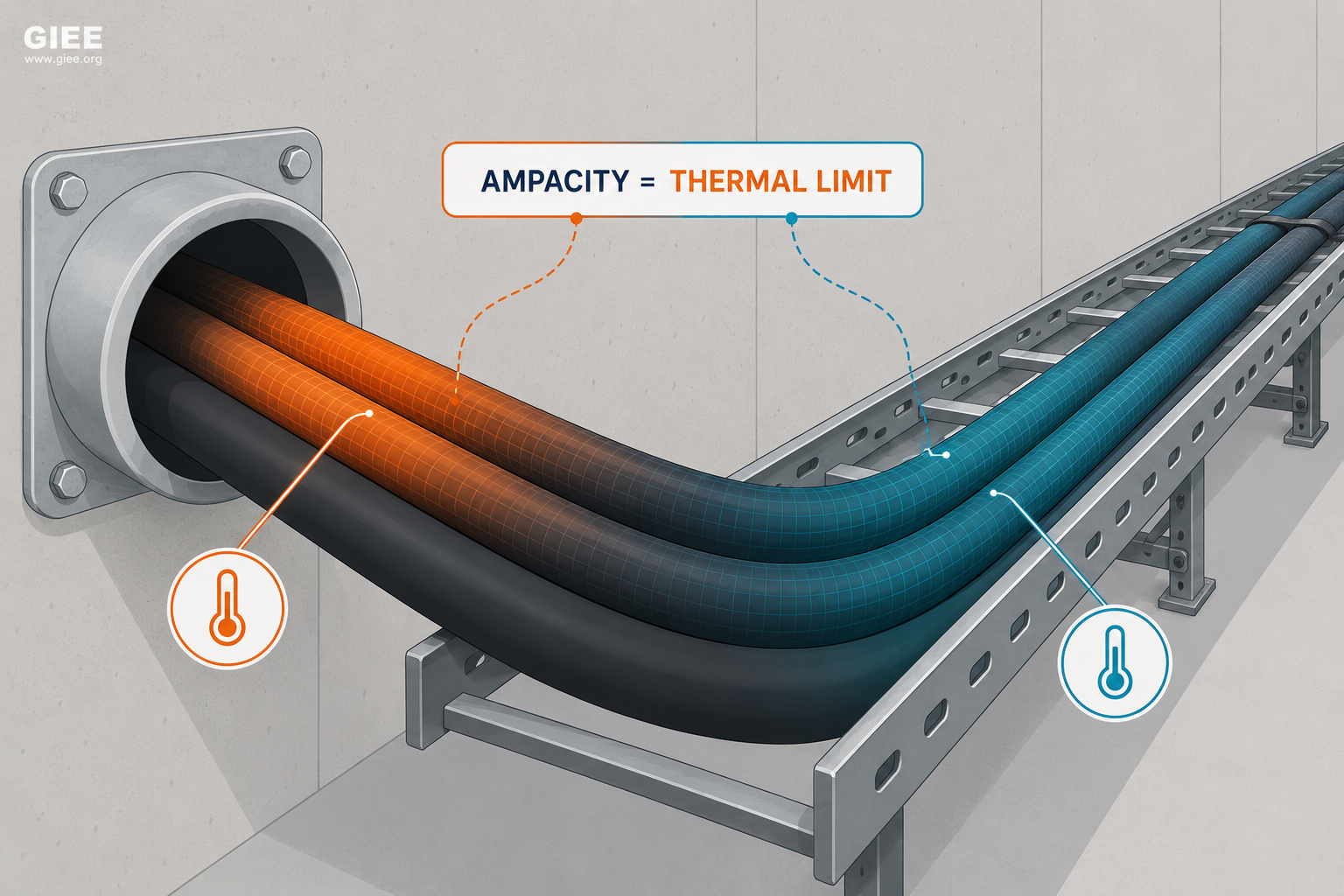
- Ampacity is a thermal limit, not an electrical one: it is the current at which the conductor reaches its insulation’s maximum rated temperature in steady state.
- The same cable can carry very different currents depending on ambient temperature, installation method, grouping, and surrounding medium.
- Heat dissipation is the governing variable – anything that traps heat lowers ampacity, and anything that removes heat raises it.
- Conductor material, conductor size, and insulation temperature class set the baseline; the installation environment then corrects that baseline up or down.
- Treating a manufacturer’s table value as universal is one of the most common and most expensive mistakes in cable engineering.
Ampacity Is a Thermal Limit, Not a Fixed Number
In a previous article we established what cable ampacity is: the maximum continuous current a conductor can carry without its temperature exceeding the limit its insulation can tolerate. That definition is precise, but it hides a practical truth that catches engineers out on real projects. Ampacity is not a property of the cable alone. It is a property of the cable and the conditions it operates in.
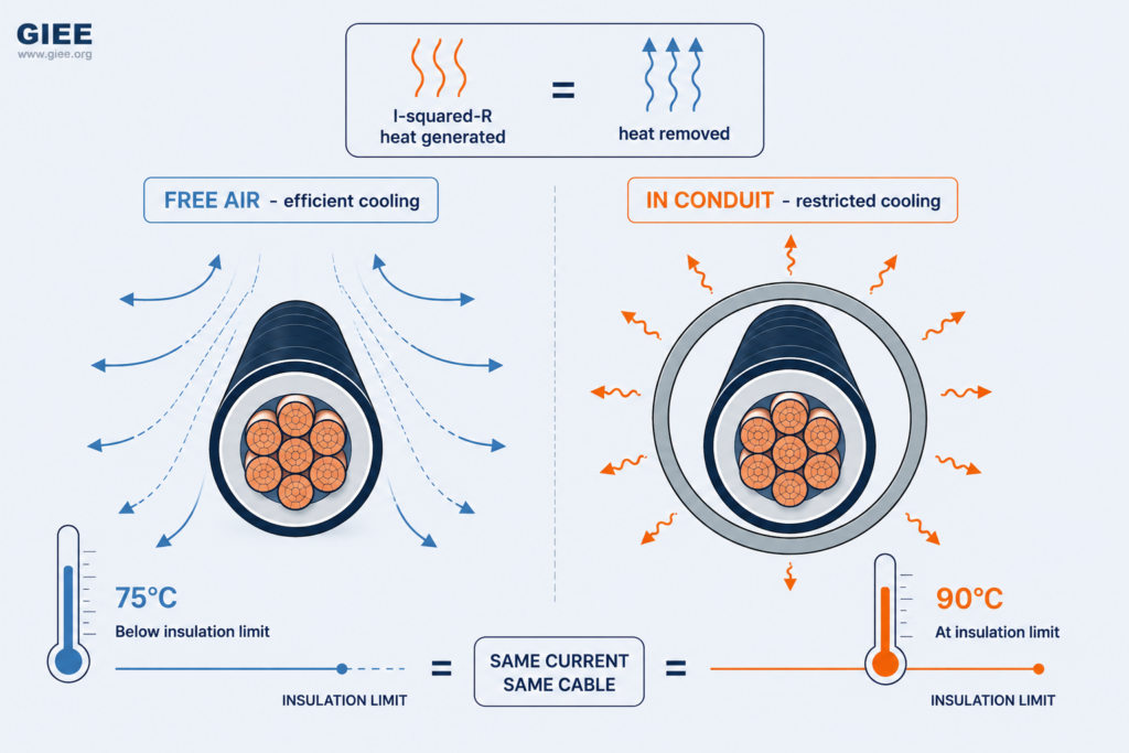
The reason is physical. When current flows through a conductor it dissipates power as heat, governed by the familiar I²R relationship. That heat raises the conductor temperature until the rate of heat generated equals the rate of heat removed to the surroundings. Ampacity is simply the current at which that equilibrium temperature lands exactly on the insulation’s rated limit – 70°C for standard PVC, 90°C for cross-linked polyethylene (XLPE), and so on.
Change the environment and you change how easily heat escapes. Bury the cable, bundle it with others, push it onto a hot rooftop, or seal it inside a conduit, and the same conductor reaches its temperature limit at a lower current. This is why interconnection studies, plant designs, and renewable projects apply correction and grouping factors on top of a base rating, following methods such as IEC 60287 and the Neher-McGrath approach behind NEC Article 310. The base number is only the starting point.
The Role of Heat Dissipation
Every ampacity question is, at heart, a heat balance question. The conductor generates heat at a rate proportional to I²R; the surroundings carry that heat away by conduction through the insulation and sheath, then by convection and radiation into air, or by conduction into soil for buried runs. When generation and dissipation balance, the conductor sits at a stable temperature.
If you raise the current, generation rises with the square of current while dissipation rises only roughly linearly with the temperature difference between the conductor and its surroundings. The conductor therefore climbs to a new, higher equilibrium temperature. Ampacity is the current that places that equilibrium right at the insulation limit, leaving no margin for further heating.
This framing explains the central puzzle of the article title. Two identical cables, same gauge, same insulation, same manufacturer, can have markedly different ampacities because their ability to shed heat differs. One in free air with good airflow sheds heat readily and tolerates more current. The other in a sealed conduit inside a hot mechanical room shares the same heat-generation curve but a far worse dissipation path, so it reaches its limit sooner. Nothing about the copper changed – only the route the heat takes to leave.
Ambient Temperature
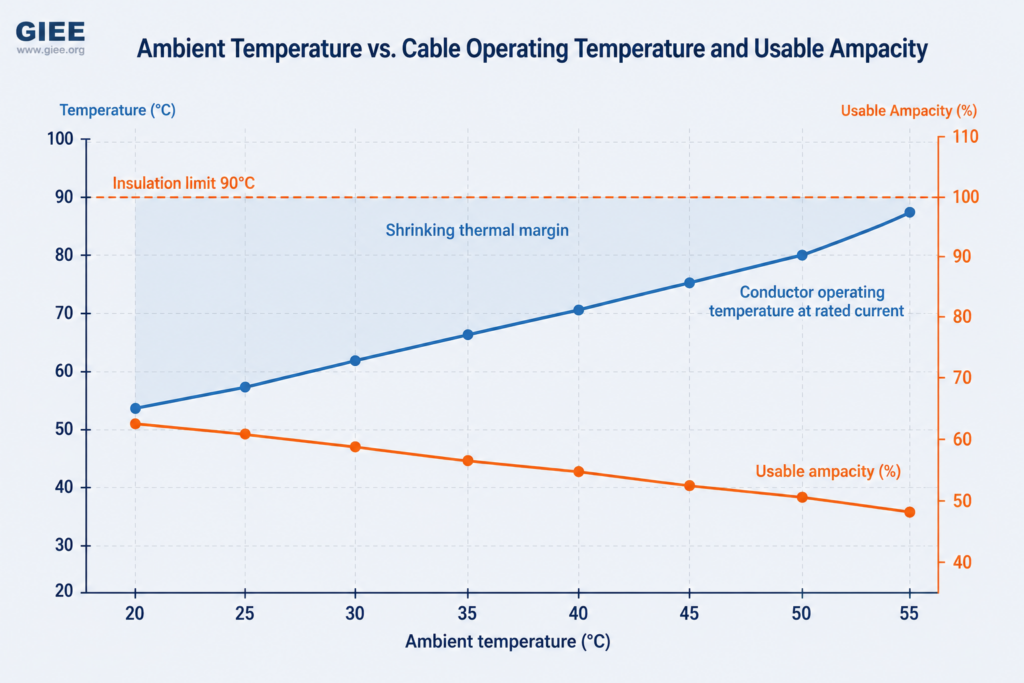
Ampacity depends on the temperature difference between the conductor and its surroundings, so the surrounding temperature directly sets the ceiling. A cable rated to 90°C in a 30°C ambient has a 60°C temperature window to work with. Place the same cable in a 50°C environment and that window shrinks to 40°C – roughly a third less driving force for heat removal, and a correspondingly lower ampacity.
Standard tables are built around reference ambients – commonly 30°C for air and 20°C for soil in IEC practice. Real installations rarely match those references. Industrial process areas, boiler rooms, and switchrooms can run far hotter. Rooftop conduits in direct sun can reach internal air temperatures well above the shaded ambient, which is why the NEC has historically required engineers to add a temperature adder for raceways exposed to sunlight on rooftops. Outdoor cables in desert solar sites face both high air temperature and intense solar gain on the cable surface.
The practical consequence is that two installations of the same cable in Reykjavik and in Riyadh are simply not the same engineering problem. Ambient temperature is the first correction factor any competent design applies, and it is the one most easily overlooked when an engineer copies a value from a generic table.
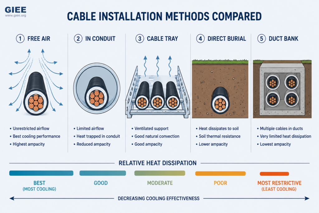
Installation Method
How a cable is physically routed governs its dominant heat-transfer path, and the differences are large. The same conductor can vary by a wide margin in ampacity across these methods:
Free air. Cables suspended or spaced in open air enjoy convection and radiation on all sides. This is generally the most favourable condition, and free-air ratings are typically the highest for a given conductor, provided the spacing between cables is maintained so they do not heat one another.
In conduit. Enclosing a cable in conduit traps a layer of still air and adds a thermal barrier. Convection is suppressed, and the conduit wall must conduct heat before the surrounding air can take it. Conduit ratings are noticeably lower than free-air ratings, and a conduit packed near its fill limit is worse still.
Cable tray. Trays sit between free air and conduit. A single layer of well-spaced cables on a ventilated ladder tray cools nearly as well as free air. Stack cables in multiple layers or use a solid-bottom tray, and the inner cables lose their cooling path and the effective rating drops.
Direct burial. Buried cables rely on conduction into the soil. The decisive variable here is the soil’s thermal resistivity, which depends heavily on moisture content and composition. Dry sandy backfill conducts heat poorly and can dramatically reduce ampacity; engineered thermal backfill is sometimes specified to manage this.
Duct banks. Cables pulled into ducts encased in concrete face the most restrictive condition of all in many designs. Heat must cross the air gap to the duct wall, through the concrete, and into the surrounding soil, while neighbouring ducts in the same bank heat one another. Duct-bank ampacity calculations are correspondingly the most involved.
Engineering Insight
Two engineers can pull the same cable from the same reel and land on ampacities that differ by 30% or more, simply because one routed it in open tray and the other in a buried duct bank. Neither is wrong – the cable is identical, but the thermal problem is not. Always state the installation method alongside any ampacity figure; a number without its method is meaningless.
Cable Grouping and Bundling
A cable does not exist in isolation. When several current-carrying cables run close together, each one is a heat source for its neighbours. Heat that one cable would normally shed into cool surroundings instead meets warm air or warm soil already loaded by adjacent cables. The mutual heating raises every conductor’s temperature, so each cable in the group reaches its limit at a lower current than it would alone.
This is why standards apply grouping or bundling factors. The more cables you pack together, and the more tightly you space them, the larger the reduction. A bundle of nine cables tightly tied together may need each one derated substantially compared with a single isolated run. Maintaining spacing – even a single cable diameter between runs – meaningfully reduces the penalty by giving heat somewhere to go.
The pattern shows up everywhere. In commercial buildings, riser shafts and cable trays crowded with feeders run hotter than the single-circuit assumptions behind a quick table lookup. On solar farms, DC string cables and AC collection cables routed together in trenches or trays heat one another under full midday production. In industrial plants, motor feeders bundled into shared raceways during a retrofit can quietly overheat if the grouping was never reassessed.
Conductor Material
The two dominant conductor materials, copper and aluminum, behave differently enough that the choice ripples through every downstream factor. Copper has higher electrical conductivity, so for a given cross-section it has lower resistance, generates less heat per amp, and supports a higher ampacity. Aluminum has roughly 61% of copper’s conductivity, so an aluminum conductor must be larger – typically one to two standard sizes up – to match a copper conductor’s ampacity.
That does not make aluminum inferior; it makes it a different trade-off. Aluminum is far lighter and cheaper per unit of current carried, which is why utility overhead lines and large feeders are overwhelmingly aluminum. Copper dominates where space is constrained, terminations are dense, or mechanical robustness matters. Aluminum also demands more attention at terminations because of its oxide layer and tendency to creep under thermal cycling, which is why proper lugs, antioxidant compounds, and correct torque are not optional.
| Property | Copper | Aluminum |
|---|---|---|
| Relative conductivity (IACS) | ~100% | ~61% |
| Size for equal ampacity | Baseline | ~1 to 2 sizes larger |
| Weight per unit current | Higher | Roughly half of copper |
| Relative material cost | Higher | Lower |
| Termination care | Straightforward | Oxide and creep management required |
| Typical applications | Dense terminations, constrained spaces, control and instrumentation | Overhead lines, large feeders, utility distribution, long runs |
Conductor Size and Surface Area
It is tempting to assume that doubling a conductor’s cross-section doubles its ampacity. It does not. A larger cross-section lowers resistance and so reduces heat generated per amp, which helps. But the conductor’s ability to shed that heat depends on its surface area, and surface area grows more slowly than cross-sectional area as the conductor gets bigger. Cross-section scales with the square of the radius; circumference scales only linearly with the radius.
The result is diminishing returns. Each step up in size buys progressively less additional ampacity per unit of added metal. This is one reason engineers often prefer multiple parallel conductors over a single very large one for high currents: several smaller conductors present far more total surface area for cooling and are easier to install. Above a certain size, simply going bigger is an inefficient way to gain current capacity.
Insulation Type and Temperature Rating
Insulation does not carry current, but it sets the temperature ceiling that defines ampacity. A conductor insulated with a material rated to 90°C can be pushed harder than the same conductor insulated to only 70°C, because it is allowed to run hotter before reaching its limit. This is why two cables with identical copper cross-sections can carry different currents purely on the strength of their insulation system.
Common insulation systems span a wide temperature range. PVC remains widespread for general wiring at 70°C. Thermoset materials such as XLPE and ethylene propylene rubber (EPR) dominate power applications at 90°C continuous, with higher short-circuit tolerance. Specialty insulations such as silicone rubber and mineral insulation reach far higher, for fire-rated and high-temperature service. The higher rating is not free – higher-temperature insulation tends to cost more and the surrounding equipment and terminations must also be rated for the temperature, which often becomes the true limiting factor.
| Insulation | Typical continuous rating | Typical use |
|---|---|---|
| PVC | 70°C | General-purpose building and low-voltage wiring |
| XLPE (cross-linked polyethylene) | 90°C | Power cables, MV and LV feeders, renewable collection |
| EPR (ethylene propylene rubber) | 90°C | Flexible power cables, MV systems, harsh environments |
| Silicone rubber | ~150–180°C | High-temperature and fire-resistant circuits |
| Mineral insulation (MI) | up to ~250°C | Fire survival, critical and high-temperature service |
Renewable Energy Applications
Renewable projects concentrate almost every ampacity stressor into one site. In rooftop solar PV, DC and AC cables run across hot roof surfaces where surface temperatures can far exceed the ambient air, conduits sit in direct sun, and conductors are frequently bundled along racking and into combiner boxes. The current is also highly correlated with the heat: cables carry their peak load precisely when the sun is strongest and the rooftop is hottest, so the worst electrical and worst thermal conditions coincide.
Battery energy storage systems (BESS) bring sustained high-current charge and discharge cycles, often in enclosed containers where heat management is already a design challenge. Cable routing inside a battery enclosure shares the thermal budget with the cells themselves, and a poorly cooled cable run can become a hidden bottleneck. Utility-scale solar and wind sites add long collection runs in trenches and duct banks, where grouping and soil thermal resistivity dominate, and where underrating the cable means buried, costly rework.
The lesson for renewable engineers is that the generic table value is almost never the design value. High ambient, solar gain, grouping, and coincident peak loading all push in the same direction – toward lower real-world ampacity than the catalogue suggests.
Engineering Insight
On a renewable site, the cable’s hardest moment is not an abstract worst case – it is a clear, hot afternoon at full output. Design for that coincident condition, not for a comfortable spring morning, and the cable will hold up for its service life.
Common Engineering Mistakes
The recurring failures in cable engineering are rarely exotic. They cluster around a handful of habits:
- Ignoring ambient temperature. Applying a 30°C reference value to a 50°C environment overstates ampacity and shortens insulation life.
- Overlooking grouping. Sizing each circuit alone, then routing many together, so mutual heating goes uncorrected.
- Assuming manufacturer data applies everywhere. Catalogue ratings are quoted for specific reference conditions, not for your installation.
- Treating ampacity as a fixed value. Forgetting that the same cable has different ratings in different routes, and reusing one number across a whole design.
Each of these is a version of the same root error: detaching the cable from its environment. The cure is discipline – always pair an ampacity figure with the conditions it assumes.
Real-World Examples
Rooftop solar, derated by the roof. A commercial rooftop PV array used AC feeders sized from a standard 30°C table. Once commissioned, the conduits sat on a dark membrane roof reaching surface temperatures well above 60°C in summer. The conductors ran far hotter than designed, and the circuits had to be reconductored to a larger size to restore margin – a cost that an ambient correction at design stage would have avoided.
Industrial retrofit, bundled into trouble. A plant expansion pushed several new motor feeders through an existing, already-full cable tray. Each feeder was correctly sized in isolation, but the added grouping raised conductor temperatures across the whole tray. The symptom showed up as nuisance thermal alarms and accelerated insulation ageing, traced back to a grouping factor that was never applied.
Utility-scale collection in dry soil. A solar farm’s medium-voltage collection cables were buried in native sandy soil with high thermal resistivity, much worse than the moist-soil assumption behind the original rating. Under full midday output the cables approached their thermal limit. The remedy was engineered thermal backfill on future circuits and a revised loading limit on the installed ones.
Frequently Asked Questions
Is a cable’s ampacity a fixed number?
No. It is a thermal limit that depends on ambient temperature, installation method, grouping, and the surrounding medium. The same cable has different ampacities in different installations.
Why do hotter environments reduce ampacity?
Ampacity depends on the temperature difference between the conductor and its surroundings. A hotter environment shrinks that difference, so less current is needed to reach the insulation’s temperature limit.
Which installation method gives the highest ampacity?
Free air, generally, because the cable can shed heat by convection and radiation on all sides. Conduit, multilayer tray, direct burial, and duct banks progressively restrict cooling.
Does using aluminum instead of copper lower ampacity?
For the same cross-section, yes, because aluminum has lower conductivity. An aluminum conductor is sized up – typically one to two standard sizes – to match a copper conductor’s ampacity.
Why does a higher insulation temperature rating increase ampacity?
The insulation rating sets the maximum allowed conductor temperature. A 90°C insulation permits a higher operating temperature, and therefore more current, than a 70°C insulation on the same conductor.
Do I always have to apply derating factors?
Whenever your conditions differ from the table’s reference – higher ambient, grouped cables, restrictive installation – yes. The base rating is a starting point, not the final design value.
Why are renewable installations particularly demanding for ampacity?
They combine high ambient and solar gain, grouped cable routing, and peak current that coincides with peak heat. These stressors all push real ampacity below the catalogue value at once.
Conclusion
The single most useful idea in cable engineering is also the simplest: ampacity is governed by heat, and heat is governed by the environment. The conductor material, its size, and its insulation class set a baseline, but ambient temperature, installation method, and grouping then move that baseline – often substantially – up or down. This is precisely why the same cable does not always carry the same current.
For working engineers, the takeaways are concrete. Never quote an ampacity without its conditions. Apply ambient and grouping corrections honestly, especially on hot rooftops and crowded trays. Treat manufacturer tables as reference points, not verdicts. And on renewable sites, design for the coincident worst case of full output on a hot afternoon. Get the thermal environment right and the cable will do its job for decades; get it wrong and no amount of conductor metal will hide the mistake. To go deeper into the sizing methods behind these factors, continue with GIEE’s cable engineering resources and our coverage of interconnection and DER design.