
Key Takeaways
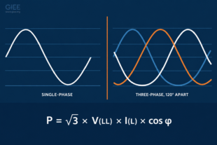
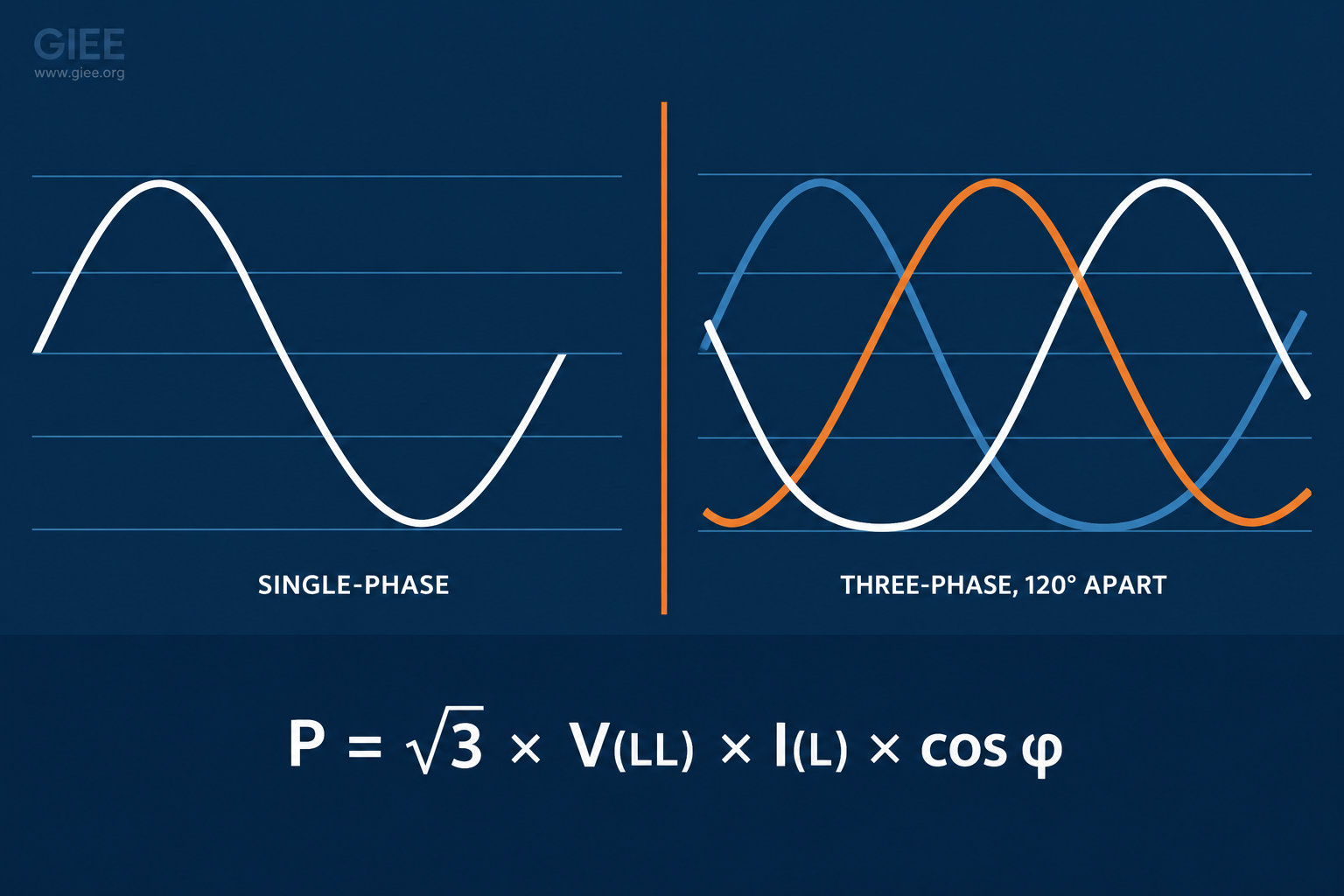
- Single-phase and three-phase systems obey the same power relationships. The only structural difference is that three-phase adds two more voltage waveforms, each displaced by 120°.
- The √3 factor is not an arbitrary constant. It is the magnitude of the phasor difference between two equal voltages 120° apart: 2 cos(30°) = √3.
- Real power is P = V × I × cosφ in single-phase and P = √3 × VLL × IL × cosφ in three-phase. Mixing line and phase quantities is the most common calculation error in the field.
- For the same load, voltage and losses, a three-phase feeder carries 42% less line current and needs roughly 25% less conductor metal than a single-phase feeder.
- These formulas assume balanced, sinusoidal conditions. Unbalance and harmonics break them in specific, predictable ways.
Ask a room of engineers to size a feeder for a 40 kW load and most will land on the same answer. Ask them why the three-phase formula carries a √3 and the single-phase formula does not, and the room gets quiet. That gap matters more than it looks, because nearly every current-calculation error that shows up in a design review traces back to the same root cause: someone mixed a line quantity with a phase quantity, or applied √3 where it did not belong.
This article walks through what actually differs between the two systems, how to calculate real power, apparent power, reactive power and current in each, and where the √3 comes from geometrically. Every relationship is backed by a worked example with real numbers. It is written for practicing engineers and technicians who need the calculations to be right the first time, and for students who want the reasoning rather than a formula sheet.
What Actually Separates the Two Systems
Single-phase: one waveform
A single-phase system delivers power using one alternating voltage waveform measured between two conductors. Voltage and current each trace a single sinusoid at 50 or 60 Hz, and all the power flows through that one waveform.
North American residential service creates a persistent point of confusion here. A 120/240 V service uses a center-tapped transformer secondary, which produces two 120 V halves that are 180° apart. This is split-phase, and it is still single-phase: both halves originate from a single transformer winding fed by one phase of the utility system. It is not two-phase. Genuine two-phase systems used a 90° displacement and are a historical curiosity, not something you will meet on a modern distribution circuit.
Three-phase: three waveforms, 120° apart
A three-phase system delivers power through three voltages of equal magnitude and frequency, each displaced by 120 electrical degrees. In a machine they are produced by three winding sets displaced by 120 electrical degrees, which corresponds to 120 mechanical degrees only in a two-pole machine. In a transformer the displacement is inherited from the supply rather than created by winding geometry. For a balanced set, the three instantaneous voltages sum to zero at every point in the cycle, and for a balanced linear load the three line currents do the same, which is why a four-wire wye system carries essentially no neutral current under those conditions.
v_a(t) = √2 × V × sin(ωt)
v_b(t) = √2 × V × sin(ωt − 120°)
v_c(t) = √2 × V × sin(ωt − 240°)

v_a + v_b + v_c = 0   at every instant, when balanced

where V is the RMS phase voltage and ω = 2πf
That is the entire structural difference. Everything else – the √3, the wye and delta connections, the conductor savings – follows from those three displaced waveforms.
Single-Phase Power: The Three Quantities That Matter
In any AC circuit, the current can lag or lead the voltage depending on how much inductance or capacitance the load contains. The phase angle between them, φ, splits the total power the source must supply into a component that does useful work and a component that only moves energy back and forth.
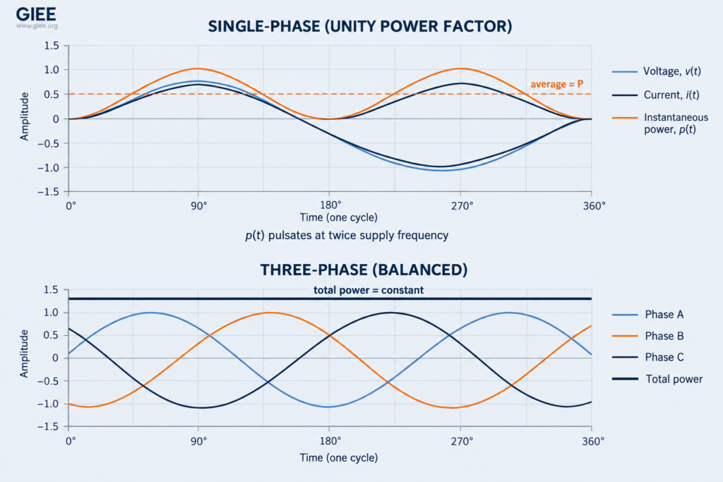
It is worth seeing why P and Q are separable in the first place. Multiply the instantaneous voltage and current waveforms together and the product contains a constant term plus a term oscillating at twice the supply frequency.
Two consequences follow. First, single-phase power delivery is never smooth: p(t) swings between P − S and P + S at twice supply frequency, 120 times per second on a 60 Hz system. At unity power factor that means it touches zero and peaks at twice its average value. That pulsation is why single-phase motors vibrate more than their three-phase equivalents. Second, whenever φ is not zero the oscillating amplitude S exceeds the average P, so p(t) goes briefly negative in each cycle, meaning energy stored in the load’s magnetic or electric field flows back to the source. That returning energy is exactly what Q measures.
Why Three-Phase Takes Over Above a Few Kilowatts
Three-phase is not simply “more power.” It solves three specific engineering problems that single-phase cannot.
Constant power delivery. Each phase produces its own pulsating power exactly as EQ 2 describes, but the three pulsations are 120° apart. Their oscillating terms cancel completely, leaving a total instantaneous power that is perfectly constant for a balanced load: ptotal(t) = 3 × Vph × Iph × cosφ. A three-phase motor therefore receives steady power and steady average torque, while a comparable single-phase motor carries a double-frequency pulsating torque component on top of its average torque. Rotor inertia smooths the shaft speed, but the pulsation still shows up as vibration and audible noise.
A rotating magnetic field for free. Three windings displaced by 120 electrical degrees, carrying currents 120° apart in time, produce a magnetic field that rotates at synchronous speed. That rotating field is what makes a three-phase induction motor self-starting with no start winding, capacitor, or centrifugal switch. A single-phase winding instead produces a pulsating field that resolves into two equal counter-rotating fields, so a single-phase induction motor develops no net torque at standstill. It needs an auxiliary winding, a capacitor or a shaded pole to create the phase displacement that gets it turning, and those are the components that most often fail.
Conductor economy. For a given power and voltage, three-phase moves the same energy with less current per conductor and less total conductor metal. Example 4 below puts numbers on this.
Phase vs. Line: The Terminology That Causes the Errors
Four quantities need to be kept apart, and confusing any two of them produces an answer that is wrong by a factor of √3 or 3.
- Phase voltage (Vph) – the voltage across one winding or one branch of the load.
- Line voltage (VLL) – the voltage between any two line conductors, also called line-to-line.
- Phase current (Iph) – the current flowing through one winding or one branch of the load.
- Line current (IL) – the current in the line conductor feeding the load. This is what a clamp meter on the feeder reads.
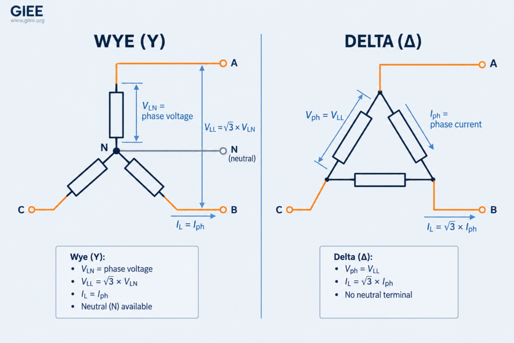
How these relate depends entirely on whether the three elements are connected in wye or delta. In a wye connection, each line conductor is in series with exactly one winding, so line current equals phase current. In a delta connection, each winding sits directly across two lines, so phase voltage equals line voltage. The √3 shows up on the other quantity in each case.
| Quantity | Wye (star, Y) | Delta (Δ) |
|---|---|---|
| Line voltage VLL | √3 × Vph, leading Vph by 30° | = Vph |
| Phase voltage Vph | VLL / √3 (line-to-neutral) | = VLL |
| Line current IL | = Iph | √3 × Iph, lagging Iph by 30° |
| Phase current Iph | = IL | IL / √3 |
| Neutral available | Star point exists; brought out as a neutral in four-wire systems, left isolated or grounded only in three-wire systems | No inherent neutral point; one can be derived by center-tapping a winding (240/120 V high-leg) or with a grounding transformer |
| Three-phase real power | √3 × VLL × IL × cosφ | identical expression |
| Typical use | 208Y/120 V and 480Y/277 V secondaries, any load needing single-phase taps and a grounded neutral | Motor windings, medium-voltage transformer primaries, three-wire loads, traps triplen harmonics in circulation |
Note the notation convention while you are here. When a three-phase system is described by a single number such as “480 V”, that figure is the line-to-line value by convention unless the context says otherwise. Individual single-phase loads are still named by the voltage they actually see, which is why a lighting circuit fed line-to-neutral from that same system is called a 277 V circuit. “480Y/277 V” tells you the connection is wye, the line voltage is 480 V and the line-to-neutral voltage is 277 V. Getting this right at the specification stage prevents most of the downstream arithmetic errors.
Where the √3 Actually Comes From
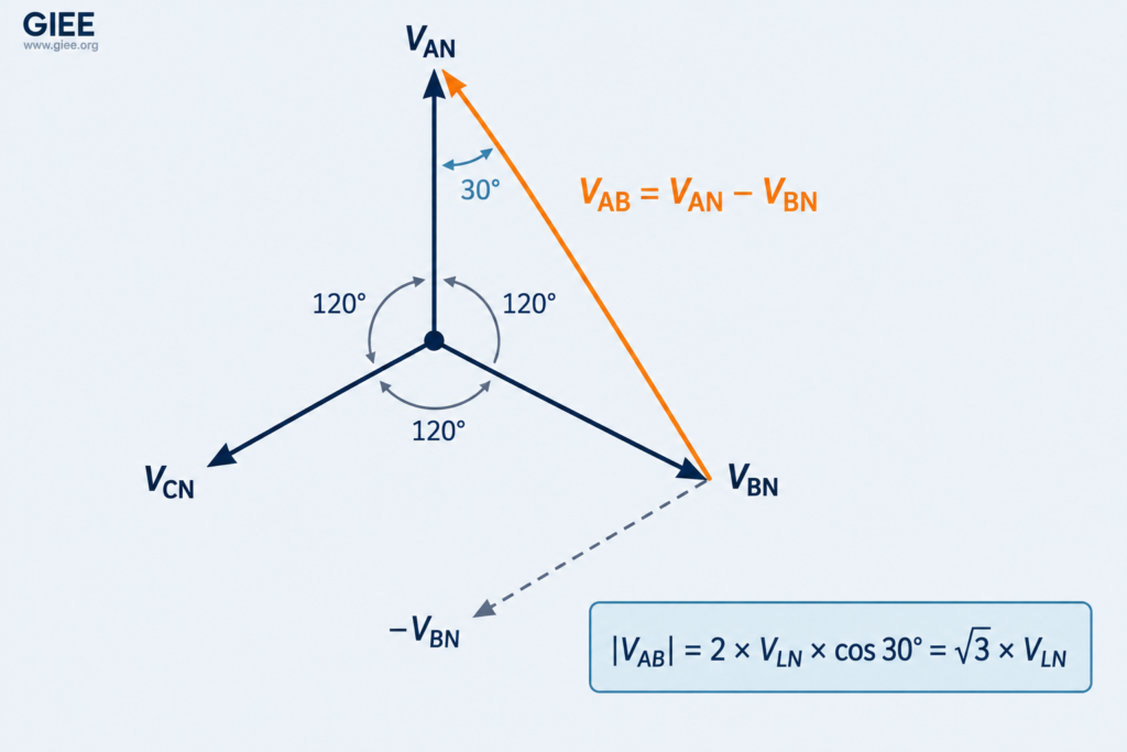
The √3 is pure geometry. Consider a wye-connected source with three line-to-neutral voltages of equal magnitude V, spaced 120° apart. The line-to-line voltage between phases A and B is not the sum of two voltages and it is not twice one of them. It is the phasor difference:
VAB = VAN − VBN
Draw those two phasors tail to tail with 120° between them, then draw the difference. You get an isosceles triangle with two sides of length V and an apex angle of 120°, so the two base angles are 30° each. The length of the base, which is the line voltage, is twice the projection of one side onto it:
Check it against a system you know: 480 / √3 = 277 V, and 208 / √3 = 120 V. Those are exactly the line-to-neutral voltages of the 480Y/277 V and 208Y/120 V systems in your panel schedules. The same construction runs in mirror image on the delta side, where the line current is the phasor difference of two winding currents, giving IL = √3 × Iph lagging by 30°.
From per-phase power to the √3 formula
Three-phase real power is simply three times the power in one phase: P = 3 × Vph × Iph × cosφ. Substitute the wye relationships into that expression and the 3 collapses into a √3:
Wye:    V_ph = V_LL / √3  and  I_ph = I_L
        P = 3 × (V_LL / √3) × I_L × cosφ = √3 × V_LL × I_L × cosφ

Delta:  V_ph = V_LL  and  I_ph = I_L / √3
        P = 3 × V_LL × (I_L / √3) × cosφ = √3 × V_LL × I_L × cosφ
Both connections land on the same expression. That is the practical payoff: once you work in line quantities, you never have to know or care whether the load is wye or delta to compute its power or line current.
⚠️ Common Mistake: Applying √3 to the line-to-neutral voltage. P = √3 × VLL × IL × cosφ and P = 3 × VLN × IL × cosφ are the same equation written two ways, so you use one or the other, never a hybrid. Substituting 277 V into the √3 form gives a result 42% low; substituting 480 V into the 3 × form gives one 73% high. When a calculated current looks off by roughly 1.73, this is almost always the cause.
Calculating Three-Phase Power and Current
In practice you usually know the load and need the current, so the working form is EQ 4 rearranged.
For motors, the mechanical rating on the nameplate is output power, so efficiency has to be divided out before you touch the electrical side. Combining that step with EQ 5 gives the form most often needed on a motor schedule.
Same Elements, Different Connection, Three Times the Power
Connection choice is not cosmetic. Reconnecting the same three impedances from wye to delta triples the power they draw, because each element now sees the full line voltage instead of line voltage divided by √3, and power scales with voltage squared.
What Three-Phase Actually Saves
| Characteristic | Single-phase | Three-phase |
|---|---|---|
| Voltage waveforms | One | Three, displaced 120° |
| Current-carrying conductors | 2 (3 for split-phase with neutral) | 3, plus neutral if four-wire wye |
| Instantaneous power | Pulsates between P − S and P + S at 2f | Constant when balanced |
| Line current, 30 kW at 240 V, pf 1.0 | 125 A | 72.2 A |
| Conductor metal at equal losses | 100% (reference) | 75% |
| Motor starting | Induction types need a start winding, capacitor or shaded pole | Inherently self-starting rotating field |
| Practical range | Individual loads usually below about 10 kW; services and utility transformers reach tens of kVA and beyond | kW to hundreds of MW |
| Where you find it | Residential, light commercial, rural single-phase laterals | Commercial, industrial, generation, transmission, distribution mains |
Field Shortcuts Worth Memorizing
Because line current is inversely proportional to voltage, every standard system voltage has a fixed current-per-kVA constant. Knowing a handful of these lets you sanity-check a load calculation or a meter reading in your head before you reach for a calculator.
| System voltage | Configuration | Line amps per kVA | Line amps at 100 kVA |
|---|---|---|---|
| 120 V | Single-phase | 8.33 | 833 A |
| 240 V | Single-phase | 4.17 | 417 A |
| 208 V | Three-phase | 2.78 | 278 A |
| 480 V | Three-phase | 1.20 | 120 A |
| 600 V | Three-phase | 0.96 | 96 A |
| 4,160 V | Three-phase | 0.139 | 13.9 A |
| 13,800 V | Three-phase | 0.042 | 4.2 A (41.8 A per MVA) |
💡 Practitioner Tip: Two constants cover most low-voltage work in North America: at 480 V three-phase, line current is about 1.2 A per kVA; at 208 V three-phase, about 2.8 A per kVA. A 750 kVA, 480 V transformer therefore has roughly 900 A of secondary full-load current, and a 100 kVA, 208 V panel roughly 278 A. If a measured or calculated value misses these by more than the load’s power factor can explain, stop and check the connection assumptions before trusting the number.
Where These Formulas Stop Working
Every equation above assumes a balanced load and sinusoidal waveforms. Modern facilities routinely violate both, and it is worth knowing exactly how.
Unbalanced loads. With unequal phase loading, there is no single IL to put into EQ 4, and the √3 form gives a wrong answer. Compute per phase and add: P = VaIacosφa + VbIbcosφb + VcIccosφc. The neutral then carries the phasor sum of the three line currents rather than zero. Depending on source, feeder and neutral impedance, unbalance can also cause the phase voltages at the load to deviate from nominal. Unbalance also drives negative-sequence current into motors, causing extra heating and derating.
Non-sinusoidal currents. Variable frequency drives, rectifiers, LED drivers and switch-mode supplies draw current that is not a sine wave. With a substantially sinusoidal supply voltage, real power still comes only from the fundamental current component, so P = V × I1 × cosφ1, while apparent power uses the true RMS current: S = V × IRMS. The true power factor is then the product of the displacement factor and a distortion factor, and it can sit well below the displacement power factor a basic meter reports. A drive with cosφ1 = 0.98 and 40% current THD has a true power factor closer to 0.91.
Triplen harmonics in four-wire wye systems. Third-harmonic currents from single-phase nonlinear loads are in phase with each other across all three phases, so instead of cancelling in the neutral they add. In circuits feeding large numbers of single-phase electronic loads, measured neutral current can approach or exceed the line current, which is why shared neutrals in those systems are often upsized and why IEEE Std 519 harmonic limits are worth checking at the point of common coupling.
Nominal versus actual voltage. Calculations use the voltage the equipment actually sees, not the label. ANSI C84.1 permits utilization voltage on a 480 V nominal system to sit anywhere in a defined range, and a feeder operating 4% low draws about 4% more current for the same real power, compounding the voltage drop that caused it.
Conclusion
The difference between single-phase and three-phase calculations reduces to one honest sentence: three-phase adds two more waveforms 120° apart, and the geometry of that displacement produces a factor of √3 wherever you convert between phase and line quantities. Everything else – S, P, Q, power factor, the power triangle – is identical in both systems.
Carry three things out of this article. Know which voltage you are holding: line-to-line unless the notation says otherwise. Use P = √3 × VLL × IL × cosφ with line quantities only, and never bolt √3 onto a line-to-neutral voltage. And check every result against the amps-per-kVA constants before it leaves your desk, because a factor-of-1.73 error is the easiest one to catch and the most expensive one to miss.
If you work on feeders, motor circuits, transformer sizing or DER interconnection, these relationships are the foundation everything else sits on. GIEE’s power systems training builds from here into voltage drop and conductor sizing, symmetrical components, short-circuit analysis and protection coordination. Explore the full catalog at giee.org.